2-15
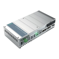
Box PC 820 / PC FI45 V2, Manual
A5E00051531-03
Pin No. DescriptionSignal
28 VCC +5V (with multifuse)
29 GND Ground
30 KDAT_EXT Keyboard data line (box connection)
31 EXTRES_N External reset
32 3,3 V +3.3 V (with multifuse)
33 3,3 V +3.3 V (with multifuse)
34 VCC +5V (with multifuse)
35 GND Ground
36 MPI MPI/DP Operation indicator
37 USB_1M –Data (USB-interface on the front)
38 USB_1P +Data (USB-interface on the front)
39 PWR_LED Power LED on the front
40 HD CD_LED Hard disk drive, active CDROM (Display LED on the front)
2.8.5 Direct Key Module (Internal Box) FI45, X45
Pin-Nr. Signal Bedeutung
1 GND Ground
2 DTAST_CLCK Clock signal for direct key module
3 GND Ground
4 DTAST_LATCH Latch signal for direct key module
5 GND Ground
6 DTAST_DAT Data signal for direct key module
2.8.6 Internal Keyboard Connection for Box PC 820, X6
Pin no. Signal Description
1 KBD_DATA Keyboard data line
2 MOUSE_DATA PS/2 mouse data line
3 GND Ground
4 VCC +5V (with multifuse)
5 KBD_CLK Keyboard clock line
6 MOUSE_CLK PS/2 mouse clock line
Motherboard
Siemens Distributor