Commissioning
4.3 Network topology
SIMATIC RF360R
20 Configuration Manual, 03/2022, C79000-G8976-C629-02
Procedure
Proceed as follows to install the reader:
1. Connect the reader to a PC or switch or to a controller using an Ethernet cable ④.
Use a connecting cable with an M12 plug (4-pin).
2. If necessary, connect the reader to another SIMATIC RF360R reader ⑤.
Use a connection cable with an M12 plug (4-pin) to loop-through PROFINET IO.
3. Connect the reader to the power supply ③ using the connecting cable.
The reader is ready for operation when the "R/S" LED is lit/flashes green. If the "R/S" LED
flashes, the reader is waiting for a connection. If the "R/S" LED is lit constantly, the reader is
connected to the controller.
You can find detailed information on mounting as well as ordering data (reader, connecting
cable, wide range power supply, etc.) in the "SIMATIC RF300" system manual.
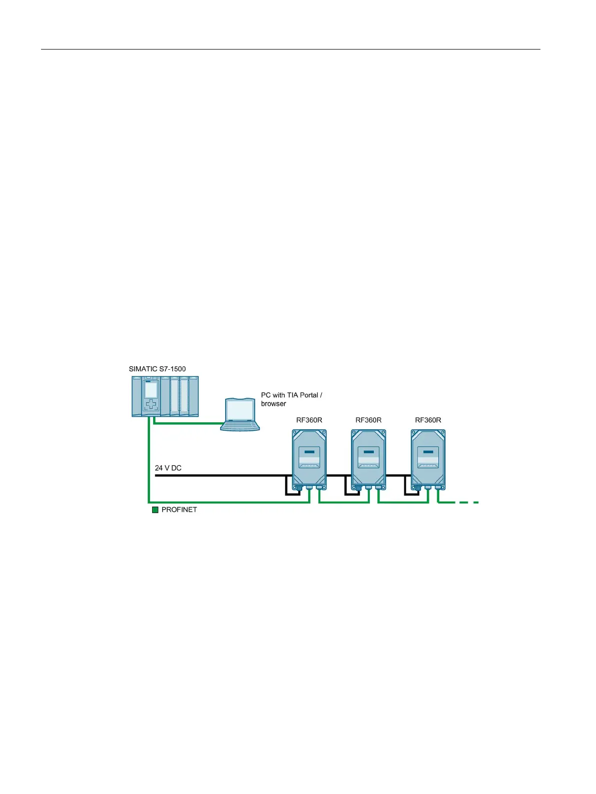
4.3 Network topology
The communication network can be designed as line/series, star or ring topology.
Figure 4-2 Configuration graphic of a line/series topology
With a linear/series topology, remember that if the communications connection of a reader to
the controller is interrupted, the communications connection to all downstream readers is
also interrupted.