Connecting hardware
3.1 The PC adapter for SIMATIC RF-DIAG
SIMATIC RF-DIAG
Operating Manual, 09/2012, C79000-G8976-C292-01
15
Pin assignment of the connecting cable between PC adapter and UHF reader
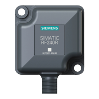
Table 3- 4 RS-422 connecting cable
View of M12 plug M12
pin
Wire color Pin assignment
1 White 24 VDC
2 Brown TX neg
3 green GND
4 Yellow TX pos
5 gray RX pos
6 pink RX neg
7 Blue Not used
8 Red Ground (shield)
Pin assignment for connection to the PC
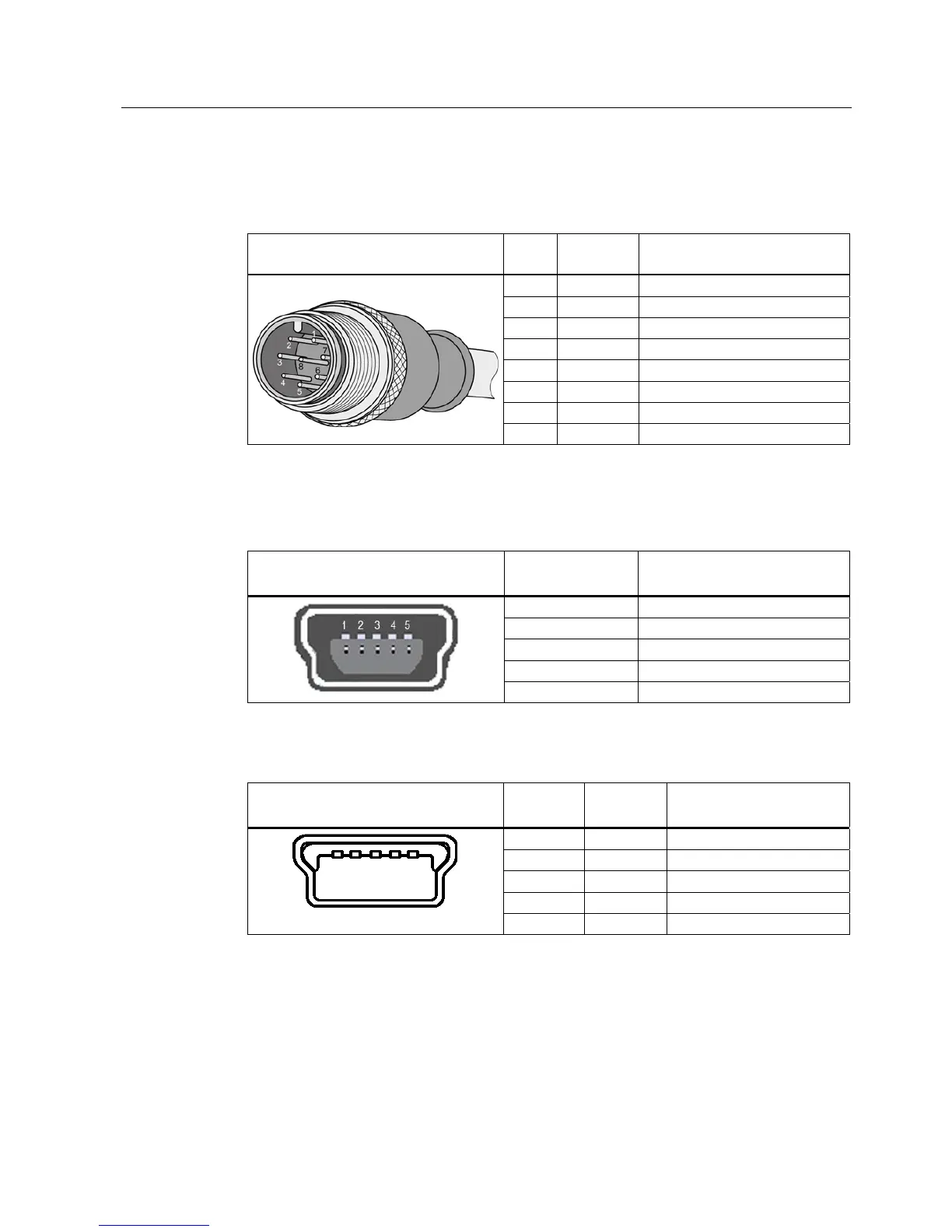
Table 3- 5 USB 2.0 mini-B connector socket of the PC adapter
View of connection socket Pin
Device side
Assignment
1 + 5 V
2 Data -
3 Data +
4 ID (not used)
5 GND
Table 3- 6 USB 2.0 mini-B plug of the connecting cable
View of mini-B plug Pin
Device side
Wire color Assignment
1 Red + 5 V
2 White Data -
3 green Data +
4 - ID (not used)
5 Black GND