LEDs and connectors
3.2 LEDs
CP 1243-1 DNP3, CP 1243-1 IEC
20 Operating Instructions, 02/2014, C79000-G8976-C312-02
The module has various LEDs for displaying the status:
●
The "DIAG" LED that is always visible shows the basic statuses of the module.
●
LEDs below the upper cover of the housing
The LEDs below the upper cover provide more detailed information on the module status.
Table 3- 1
Basic status of the module
Table 3- 2
LEDs below the upper cover of the housing
Status of the connection to Industrial Ethernet
Status of the connections to masters
- inactive -
Status of a connection for online functions
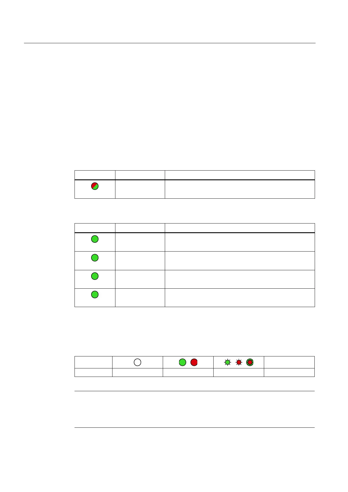
LED colors and illustration of the LED statuses
The LED symbols in the following tables have the following significance:
Table 3- 3
Meaning of the LED symbols
-
Note
LED colors when the module starts up
When
the module starts up, all its LEDs are lit for a short time. Multicolored LEDs display a
color mixture. At this point in time, the color of the LEDs is not clear.

 Loading...