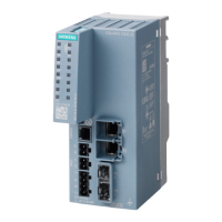
LEDs and connectors
3.2 LEDs
CP 1243-1 DNP3, CP 1243-1 IEC
Operating Instructions, 02/2014, C79000-G8976-C312-02
21
Display of the basic statuses of the CP ("DIAG" LED)
Table 3- 4 Display of the basic statuses of the CP
Meaning
(if more than one point listed: alternative meaning)
• Power OFF
• Incorrect startup
Running (RUN) without serious error
flashing green
• Partner not connected
• Firmware loaded successfully
flashing red
• Starting up
• Module fault
• Invalid STEP 7 project data
Error loading firmware
Display of the operating and communications statuses
The LEDs indicate the operating and communications status of the module according to the
following scheme:
Table 3- 5 Display of the operating and communications statuses
(red / green)
(green)
(green)
(green)
(green)
Meaning
(if more than one point listed: alternative
meaning)
•
Module startup (STOP → RUN)
•
Power OFF
red
Startup - phase 1
-
Startup - phase 2
- - - - Running (RUN) without serious error
Incorrect startup
-
- - Invalid STEP 7 project data

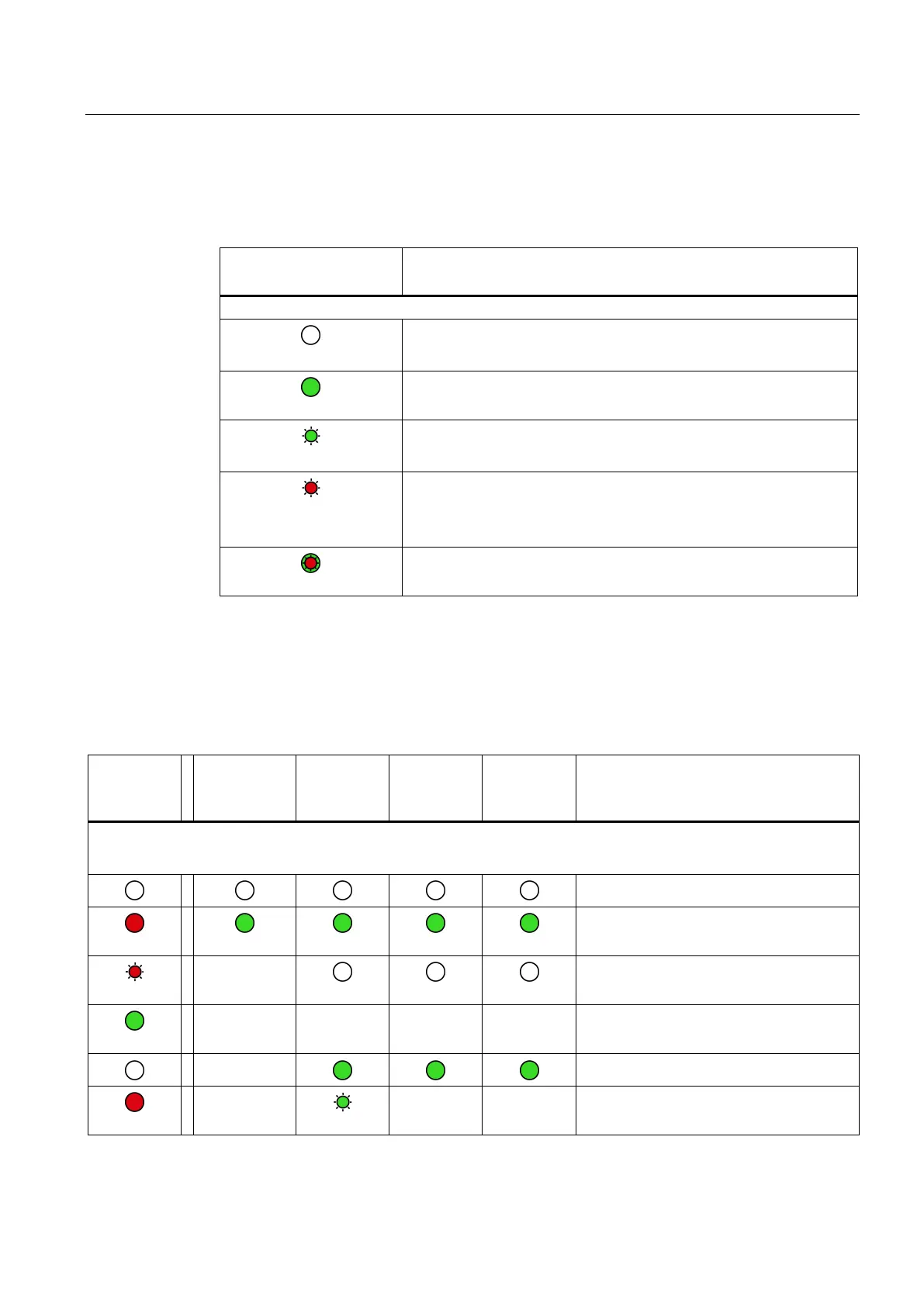 Loading...