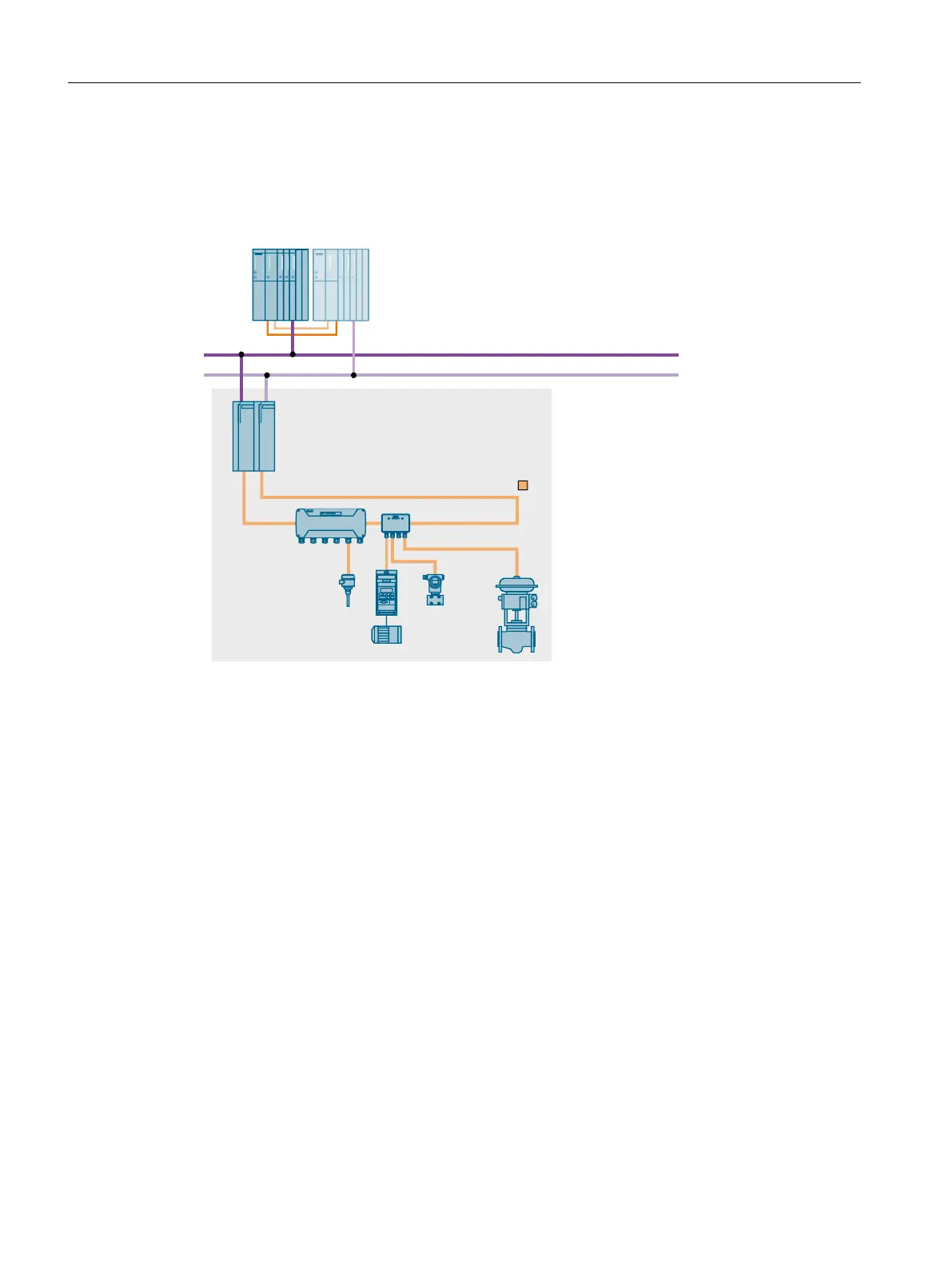
Configuration
The following figure is an example of the configuration of a bus link based on the Compact FF
Link.
+LJKDYDLODELOLW\)281'$7,21)LHOGEXV
6,0$7,&6+
$)'L6
352),%86'3
[&RPSDFW))/LQN
352),%86'3
Functionality
The bus link connects PROFIBUS DP and FOUNDATION Fieldbus with one another and
decouples various transmission rates. It is a slave on the PROFIBUS DP and master on the
FOUNDATION Fieldbus. From the point of view of the automation system, the bus link is a
modular slave. The individual modules of this slave are the field devices that are connected
to the lower-level FF segment.
The FF devices connected to the FF segment are combined at one PROFIBUS address by
the bus link.
The bus link can be connected directly to the PROFIBUS DP interface of data record gateway-
capable automation devices for the coupling between PROFIBUS DP and FOUNDATION
Fieldbus .
High availability solutions in PCS 7
4.3 Solutions for communication
High Availability Process Control Systems (V9.0)
88 Function Manual, 05/2017, A5E39221836-AA
 Loading...


