Application planning
6.6 Hardware configuration
S7-1500R/H redundant system
226 System Manual, 01/2024, A5E41814787-AF
The connection to Industrial Ethernet is interrupted.
Solution
Replace the defective CPU and the communications processor. You can find more information
on the procedure in the Replacing defective R/H CPUs (Page 446) and Replacing a defective
communications processor (Page 454) sections.
6.6 Hardware configuration
Modules suitable for R/H-CPUs
The integrated system power supply of the R/H-CPU supplies the required power for
operation. Optionally, you can also use a system power/load current supply.
The power segment overview determines the exact number of communications processors
that can be operated with the R/H-CPU. The operating principle is described in the Power
segment overview (Page 234) section.
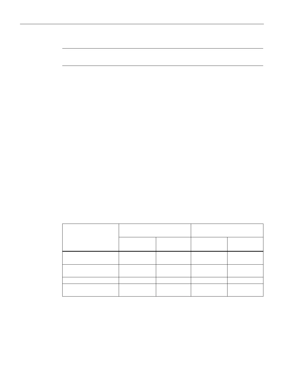
The table below shows which modules can be used in the various R/H-CPU slots:
Table 6- 5 Maximum configuration
Module type R system (primary CPU/backup
H-system (primary CPU/backup
Max. number of
Slot Max. number of
Slot
1)
(optional)
CP 1543-1
2)
1)
No connection to the backplane bus. You do not have to configure a load current supply (PM) in
STEP 7.
For R-CPUs only: When you occupy slot "0" with the system power supply (PS), you can plug in a
load current supply (PM) in STEP 7 to the left of the PS in slot 100.
2)
For the H-CPUs only possible with active backplane bus

 Loading...


