Linking and Synchronizing
6-4
Automation System S7-400H Fault-tolerant Systems
A5E00068197-07
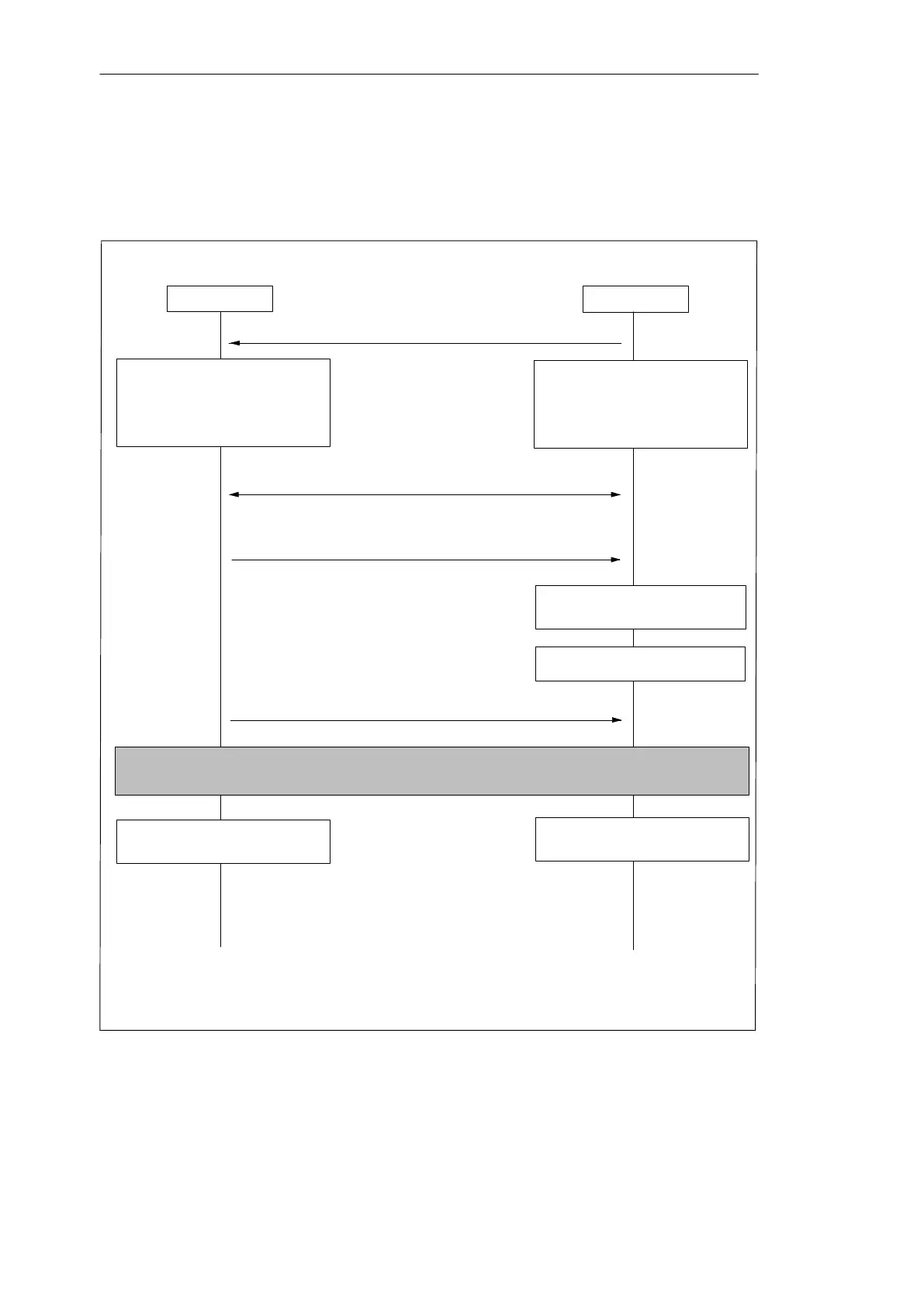
Process diagram for link-up and update
The following illustration outlines the functional sequence of link-up and update in
general terms. The starting point is with the master in single mode. In the
illustration CPU 0 is assumed to be the master CPU.
RUN
Deletion, loading, generation and
compression of blocks are no
longer possible.
Test and commissioning
functions are no longer possible.
Standby requests LINK-UP
Comparison of memory configuration, operating system ver-
sion and FEPROM content
Link-up
(REDF LEDs flash at 0.5 Hz)
STOP
All connections are
broken
Update
Redundant system mode or master/standby switch-
over with new standby put into STOP mode
Master CPU (CPU 0)
Standby CPU (CPU 1))
Copy load memory content
*)
Copy user program blocks of main memory
*)
*)
If the option “Switch to CPU with Modified Configuration” is active, no load memory
content will be copied; you can see what is copied from the user program blocks of the
main memory (OBs, FCs, FBs, DBs, SDBs) of the master CPU in Section 6.2.3.
Lift restrictions; catch up delayed
execution
Deletion, loading, generation and
compression of blocks are no
longer possible.
Test and commissioning functions
are no longer possible.
Resumption of the DP slaves
Assumption of the connections
see Figure 6-2
Lift restrictions; catch up delayed
execution
Figure 6-1 Functional sequence of link-up and update

 Loading...


