S7-400H Installation Options
2-3
Automation System S7-400H Fault-tolerant Systems
A5E00068197-07
2.1 Base System of the S7-400H
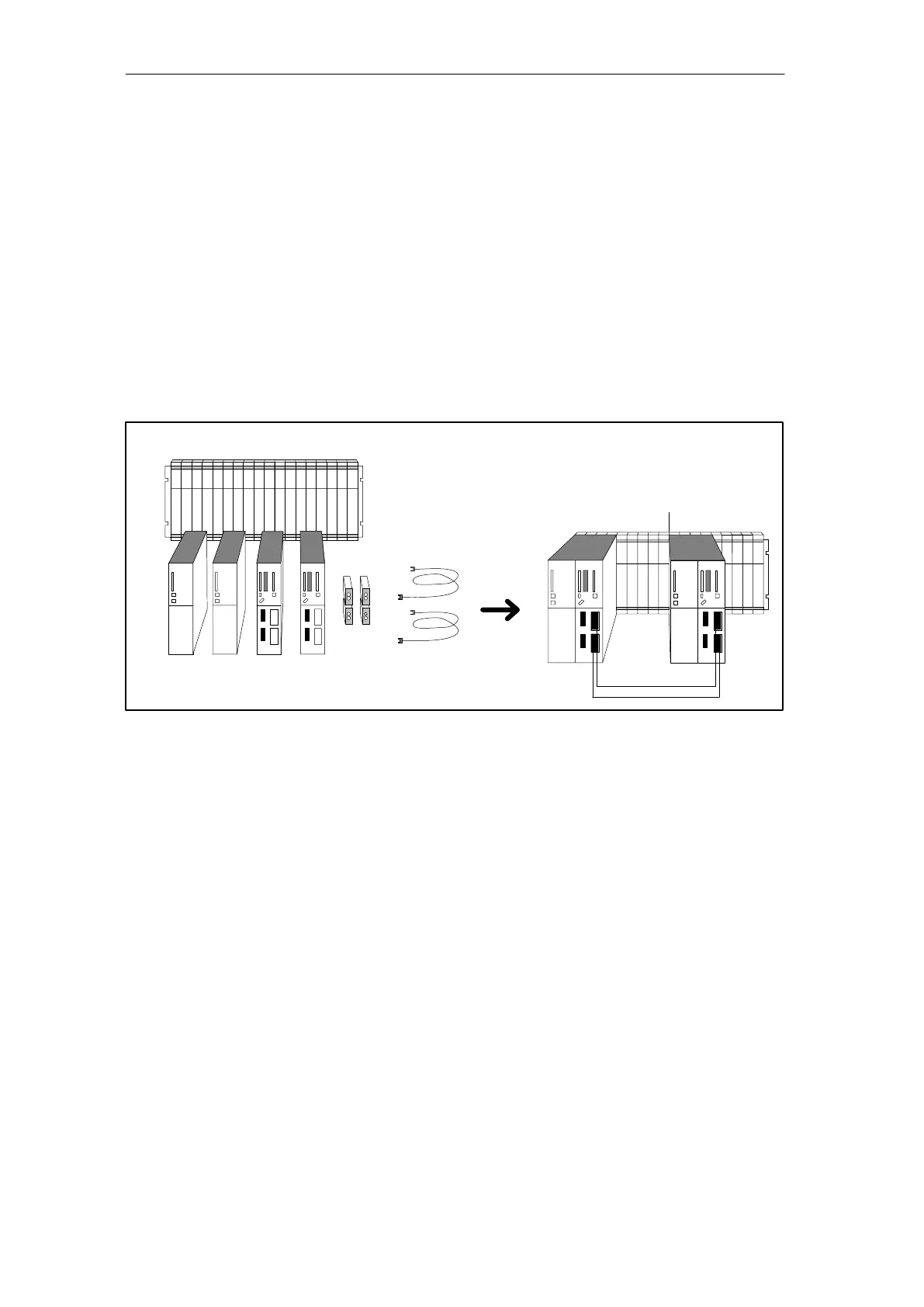
Hardware of the base system
By base system of the S7-400H we mean the minimum configuration of the
S7-400H. The base system consists of all the requisite hardware components that
make up the fault-tolerant control system. Figure 2-2 shows the components in the
installation.
You can upgrade the base system by means of standard modules from the
S7-400. There are restrictions in the case of the function and communication
processors (see Appendix E).
4 synchro-
nization
submodules
2 PS 2 CPUs 2 fiber-optic cables
Rack UR2H
S7-400H base system
Rack 0
Rack 1
Figure 2-2 Hardware of the S7-400H base system
Central processing units
At the heart of the S7-400H are the two central processing units. Setting of the
synchronization submodules, which have to be plugged into the CPU, defines the
rack numbers. In the following we will refer to the CPU in rack 0 as CPU 0,and to
the CPU in rack 1 as CPU 1.

 Loading...


