Using I/O on the S7-400H
7-18
Automation System S7-400H Fault-tolerant Systems
A5E00068197-07
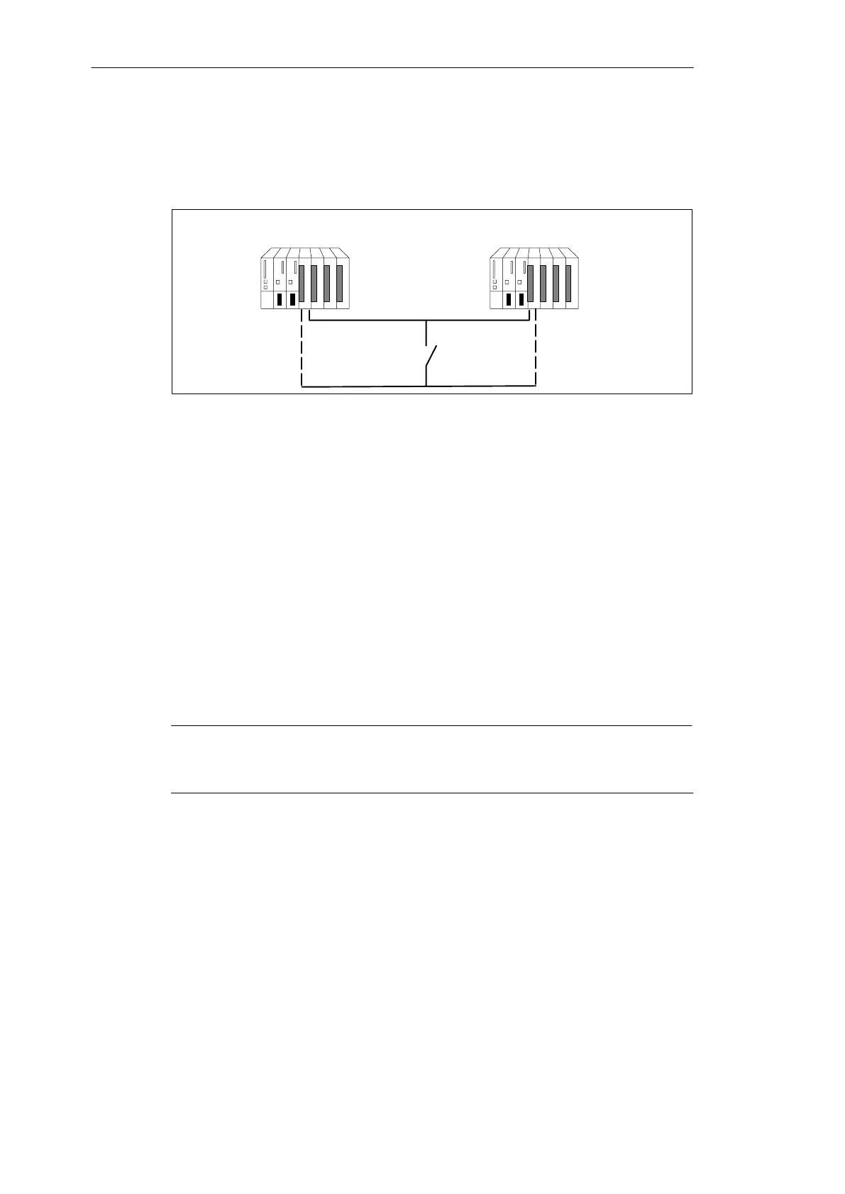
Using digital input modules with non-redundant sensor
You install digital input modules with non-redundant sensors in a 1-out-of-2
configuration:
Digital input modules
Figure 7-7 Fault-tolerant digital input module in a 1-out-of-2 configuration with one sensor
The use of redundant digital input modules increases their availability.
Discrepancy analysis detects “Continuous 1” and “Continuous 0” errors of the
digital input modules. A continuous 1 error means the value 1 is continuous at the
input, a continuous 0 error means that the input is continuously dead. This may be
caused a short-circuit after L+ or after M, for example.
Potential flow across the connection between the encoder and chassis ground of
the modules should be avoided as far as possible.
When connecting a sensor to several digital input modules, the redundant modules
have to have the same reference potential.
Connection examples are available in Appendix F and in the SIMATIC FAQs at
http://www.siemens.com/automation/service&support under the
keyword “Redundant I/O”.
Note
Note that proximity switches (Beros) have to deliver double the current listed for
single modules in the technical specifications.

 Loading...


