Connection Examples for Redundant I/O
F-5
Automation System S7-400H Fault-tolerant Systems
A5E00068197-07
F.4 SM 331; AI 8 x 16 Bit; 6ES7331-7NF00-0AB0
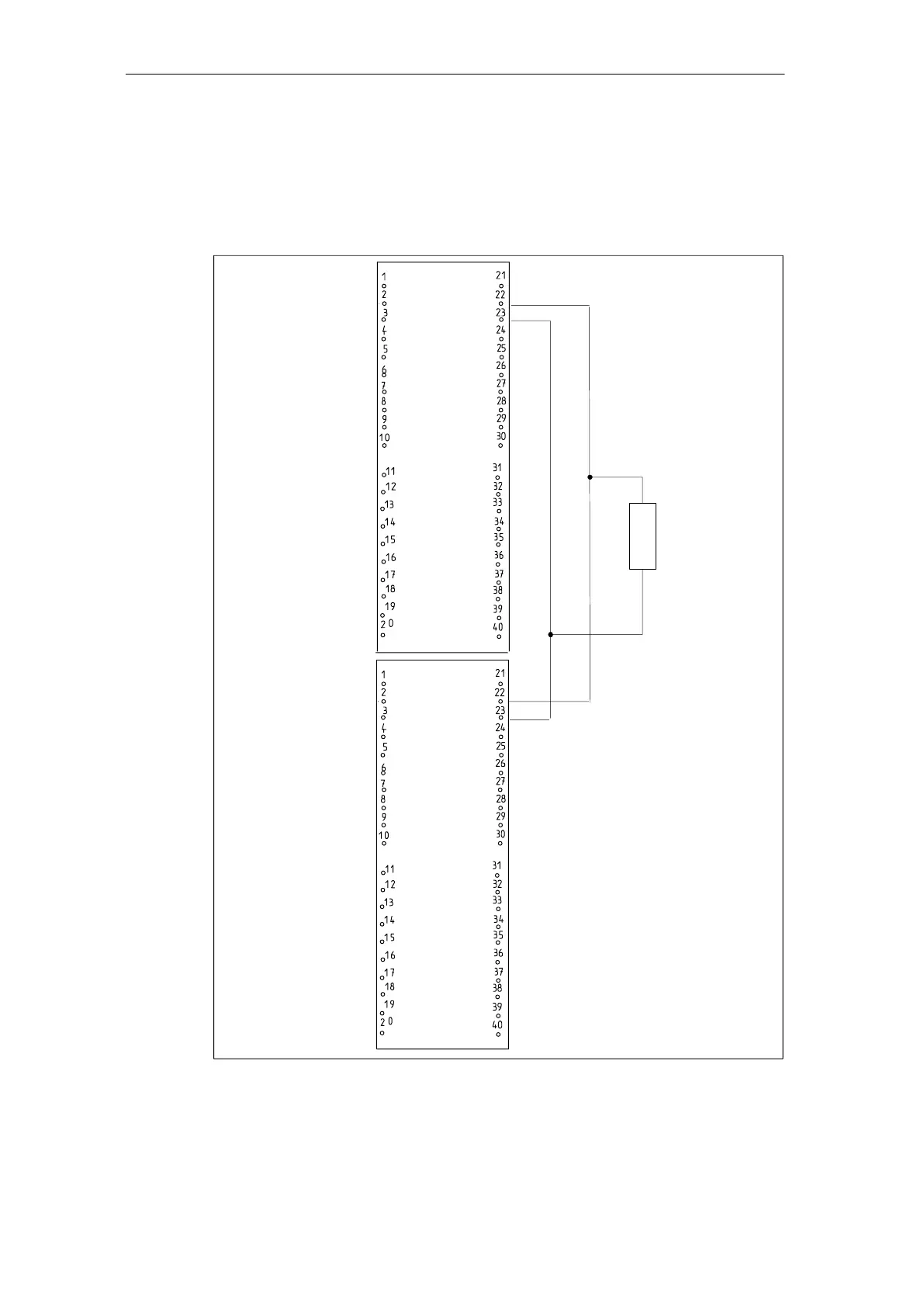
The following diagram shows the connection of a transmitter to two redundant
SM 331; AI 8 x 16 Bit. The transmitter is always connected to Channel 0.
Transmitter
+/– 10V
+/– 5V
1 – 5V
Figure F-4 Connection example SM 331; AI 18 x 16 Bit

 Loading...


