Getting Started
Fail-Safe Systems
A5E00085588-03
2-13
2.3 Fault-Tolerant S7 FH System - Getting Started
2.3.1 Fault-Tolerant S7 FH System, Setting Up the Hardware
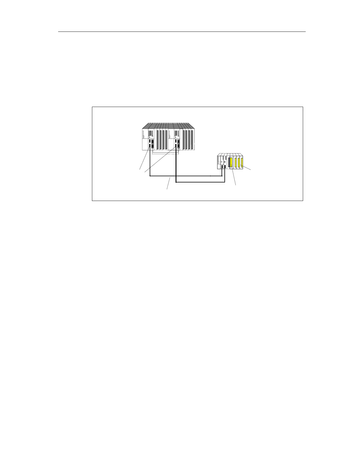
The following figure shows you an example of a hardware configuration.
S7
FH programmable controller
Redundant DP
master systems
Single-channel, switched
Fail-safe
signal modules
Profibus DP Cable
Module
For this example, you need the following hardware components:
• A programmable logic controller consisting of:
- 1 mounting rack (UR2-H)
- 2 power supplies (PS 407 10A)
- 2 CPU 417-4H
- 4 synchronization modules
- 2 fiber-optic cables
• An ET 200M distributed I/O device with an active backplane bus consisting of:
- 1 power supply (PS307 5A)
- 2 IM 153-2 Bus Interface Modules
- 1 Safety Protector Module
- 1 fail-safe digital input module (SM 326F DI 24xDC24V)
- 1 fail-safe digital output module (SM 326F DO10xDC24V/2A)
• Other accessories
- PROFIBUS cables and connectors
 Loading...


