Interface module
7.6 Interface modules SU12 und SU13
SIMATIC TDC hardware
212 System Manual, 08/2017, A5E01114865-AL
Interface modules SU12 and SU13 are used to wire a ribbon cable connector X1 on
SIMATIC TDC side 1:1 to the terminal blocks X2 on plant side, with the exception of the
following terminals.
The following signal lines are fused at the terminals (0.5 A slow-blow, internal resistance
0.25 Ω):
SU13 Pin 8, 17 – 23, 26 – 33, 36 – 43, 46 – 48
The following terminals have a protective diode (Schottky diode type Vishay BAT46) for the
24 V supply voltage of digital outputs in the following signal lines:
SU13 Pin 10
A PTC resistor (internal resistance: 0.9 Ω, e.g. type Epcos B59910-C120-A70) element is
installed at the following terminals for short-circuit protection of the 24 V supply voltage of
digital outputs in the signal line:
The concept of the interface modules support signal flow on both sides. The process signals
are transferred without additional electrical isolation and signal preparation.
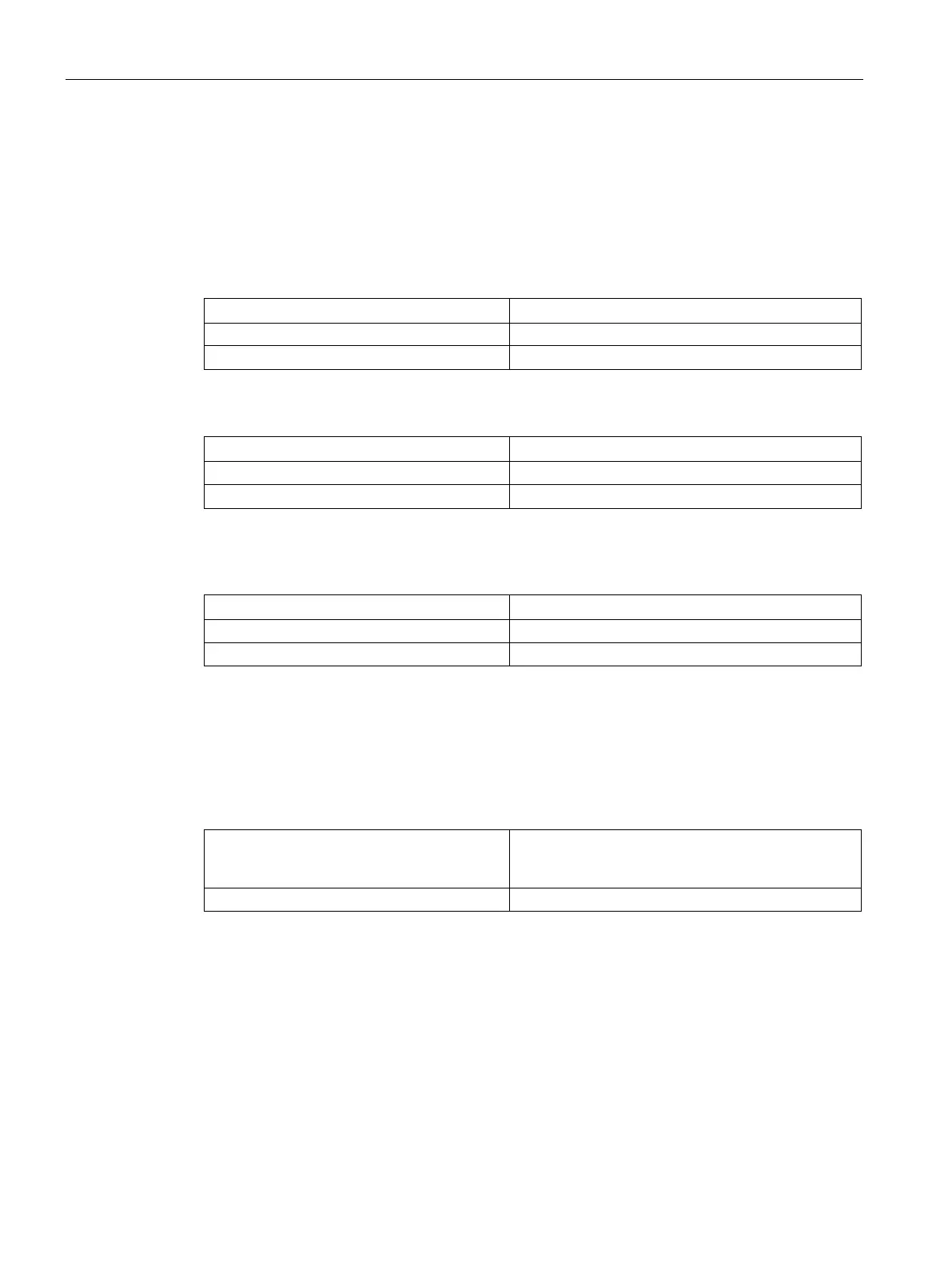
Table 7- 7 Maximum permissible voltage and current values for signal processing
Voltage range The maximum permitted voltages of the modules to
which the interface modules are connected must be