Rack
3.1 Rack UR6021 (6DD1682-0CH3)
SIMATIC TDC hardware
System Manual, 08/2017, A5E01114865-AL
41
Control and display elements
X1
3 signaling relays, 230 V AC floating potential (3 x 2 contacts)
Note
Mixed assignment
Contacts consisting of combinations of safety extra
-low voltage and hazardous voltages are
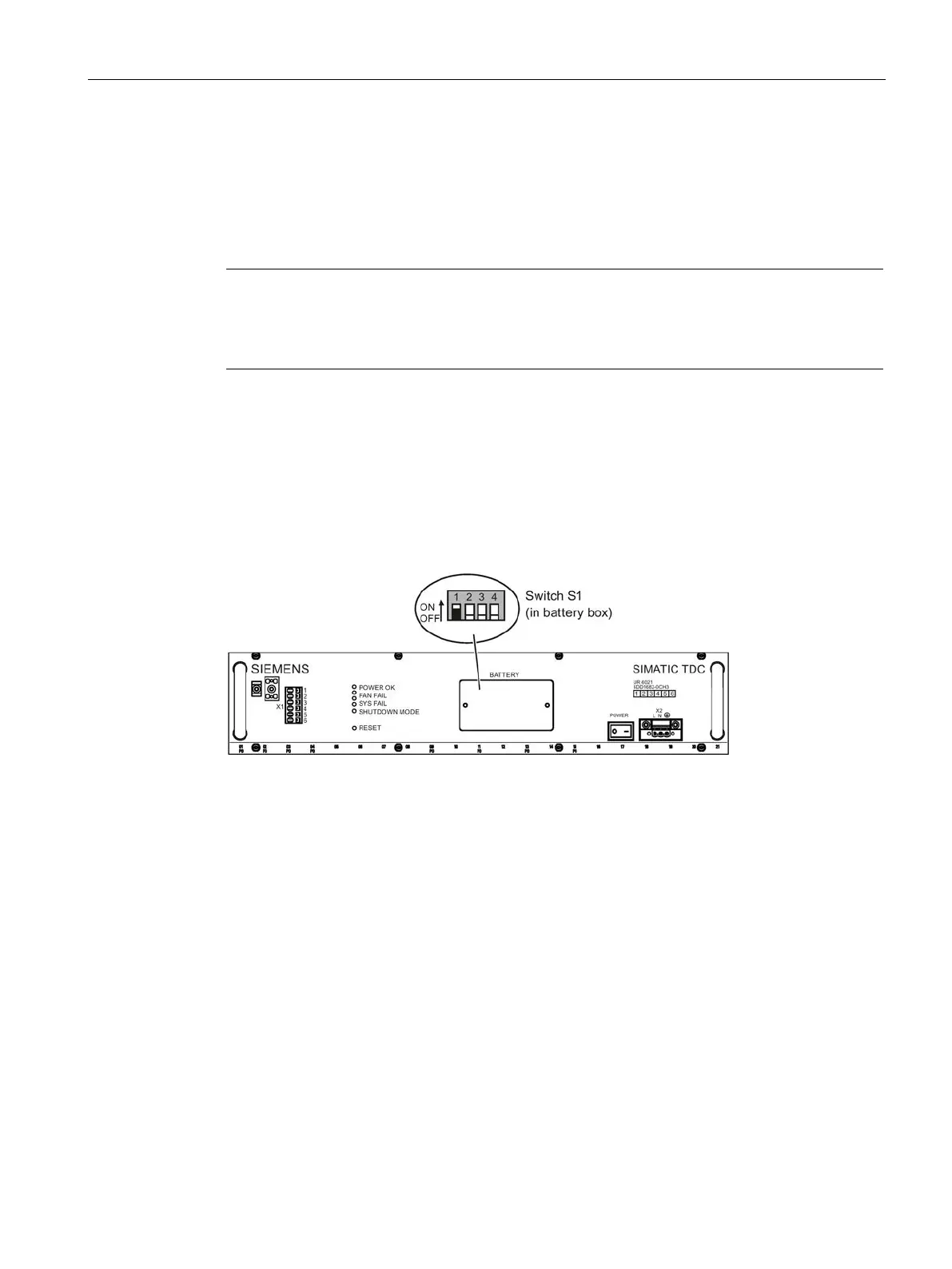
A system shutdown mode can be set in accordance with the switch position S1.1 (in the
battery compartment) as response to the failure of one or two fans.
● OFF = Shutdown on failure of two fans (SHUTDOWN MODE LED = on)
● ON = Shutdown on failure of one fan (SHUTDOWN MODE LED = flashes)
Figure 3-2 Front view of the fan tray
The four LEDs signal the operating state of the rack.
You can restart all modules by pressing the submerged pushbutton (rack RESET).
Backup battery compartment (1 x AA lithium battery)
Line voltage connection