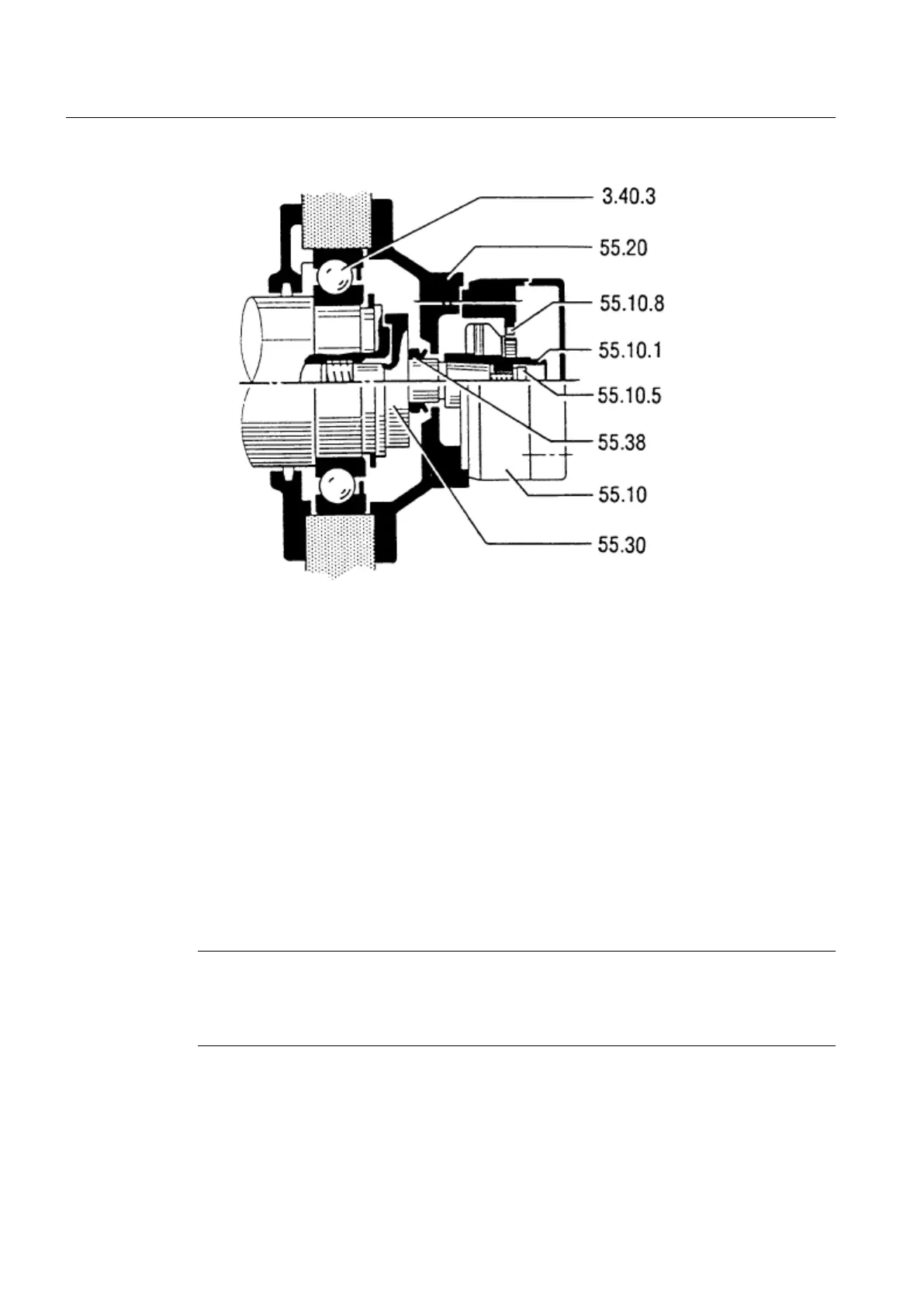
Image 9-4 Speed sensor assembly
1. Place the speed-sensor rotor on the conical shaft journal and tighten it to a torque of 10
Nm using one M6 screw.
2. Test the rotor to see if it is running smoothly. The permissible rotor deviation on the
commutator is 0.05 mm.
3. Mount the speed-sensor stator. Ensure that the brushes still have sufficient length and do
not become damaged.
9.2.6.2 Speed sensor for overhung mounting
Disassembly
With speed sensors for overhung mounting, the speed-sensor rotor is bolted to the machine
shaft journal or inserted cylindrically.
Note
Damage to the speed sensor
The speed sensor can be damaged during motor disassembly. Remove the speed sensor
before disassembling the motor.
1. Unscrew the speed-sensor stator and move it away, axially.
2. Remove the speed-sensor rotor. To do this, release the lateral set screw in the shaft journal
and pull the rotor out, axially.
Maintenance
9.2 Repair
SIMOTICS DC 1GG5
98 Operating Instructions 02/2016