3. The shaft journals or half-couplings mounted on or in the machine shaft extension must be
dismantled and replaced if they are damaged.
– When replacing damaged parts, such as the tolerance ring, please ensure they are
correctly arranged.
– Use removable LOCTITE and suitable tools to assemble parts.
4. Use a socket screw wrench to DIN 3113 (width between pivots 35 mm) to screw or unscrew
the bolt-mounted shaft journal.
Table 9-5 Recommended torques for tightening the shaft journal
Thread size Torque [Nm]
M16 20
M20 30
M24 40
Assembly
Reinstall the disassembled speed sensor and secure it in position.
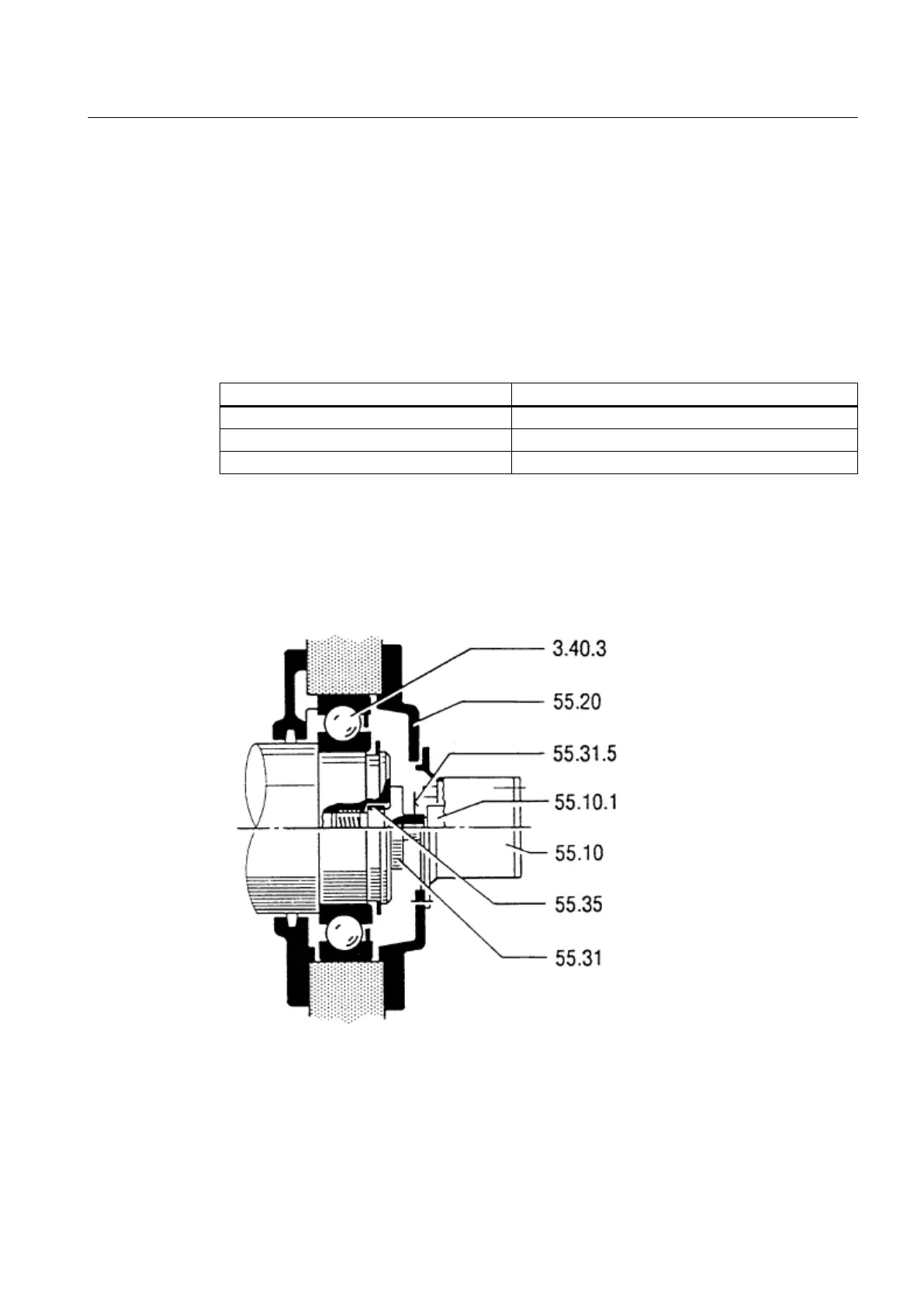
The legend numbers in the following illustration are explained in chapter Spare parts / Speed
sensor (Page 112).
Image 9-5 Speed sensor assembly
● Push the cylindrical shaft extension of the speed-sensor rotor as far as possible into the
shaft journal and secure it with the lateral set screw (M4 x 6).
● Use removable LOCTITE and a tightening torque of 13 Nm to attach the set screw.
Maintenance
9.2 Repair
SIMOTICS DC 1GG5
Operating Instructions 02/2016 99