5.5 Mounting the drive elements
Reduce the bending torque load applied to the shaft and the bearing by appropriately arranging
the output elements.
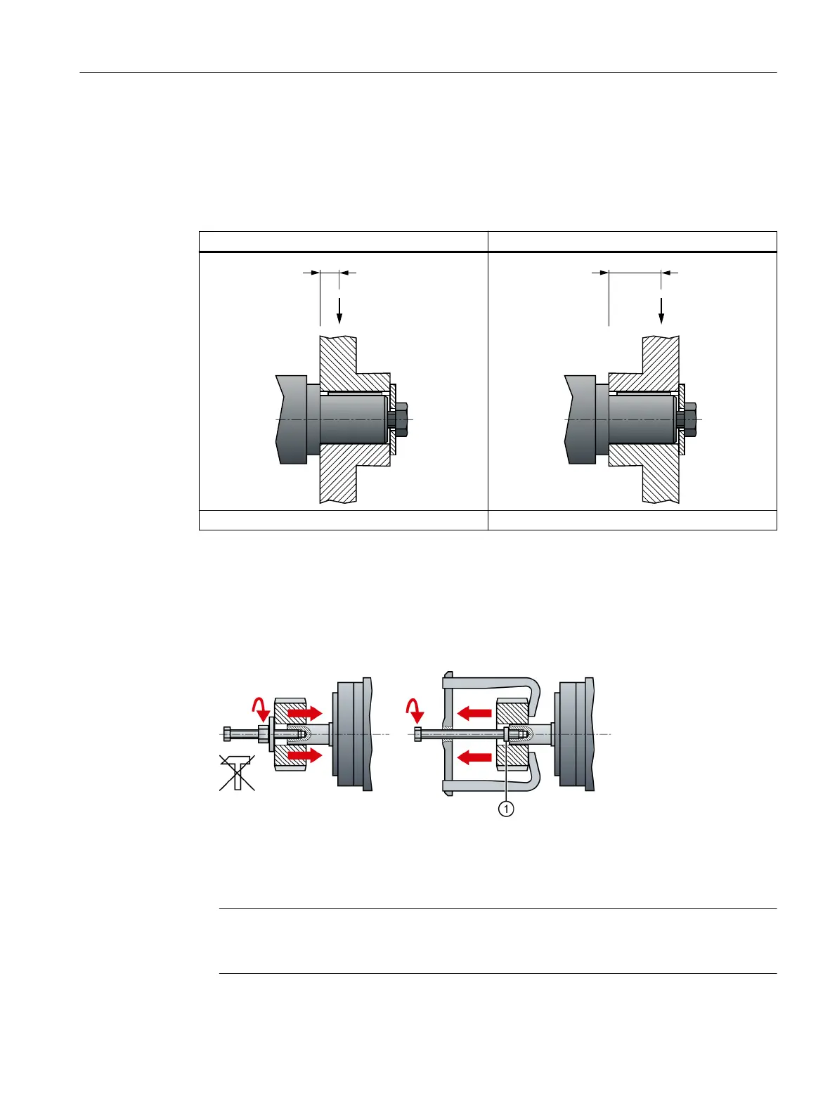
Mount the output elements as close as possible to the motor bearing.
optimum unfavorable
low stress on shafts and bearings high stress on shafts and bearings
Mount or remove the power output elements (e.g. couplings, gear wheels, belt pulleys) using
suitable devices only (see gure).
• Use the threaded hole in the shaft extension.
• If required, heat up the output elements before mounting or removing.
• When removing the output elements, use an intermediate disk to protect the centering in the
shaft extension.
1 Intermediate washer/disk (to protect the centering in the shaft extension)
Figure 5-2 Mounting and removing output elements
• If necessary, completely balance the motor together with the output elements according to
ISO 1940.
Note
Motors with feather key are half-key balanced. The motors have been balanced with half a
feather key.
The motor dimensions can be found in section "Dimension drawings (Page 107)".
Mounting
5.5 Mounting the drive elements
SIMOTICS S-1FK2 synchronous motors for SINAMICS S120
Operating Instructions, 02/2022, A5E46089564B AD 63