6.3.2 Line connection
Designs of the power connectors
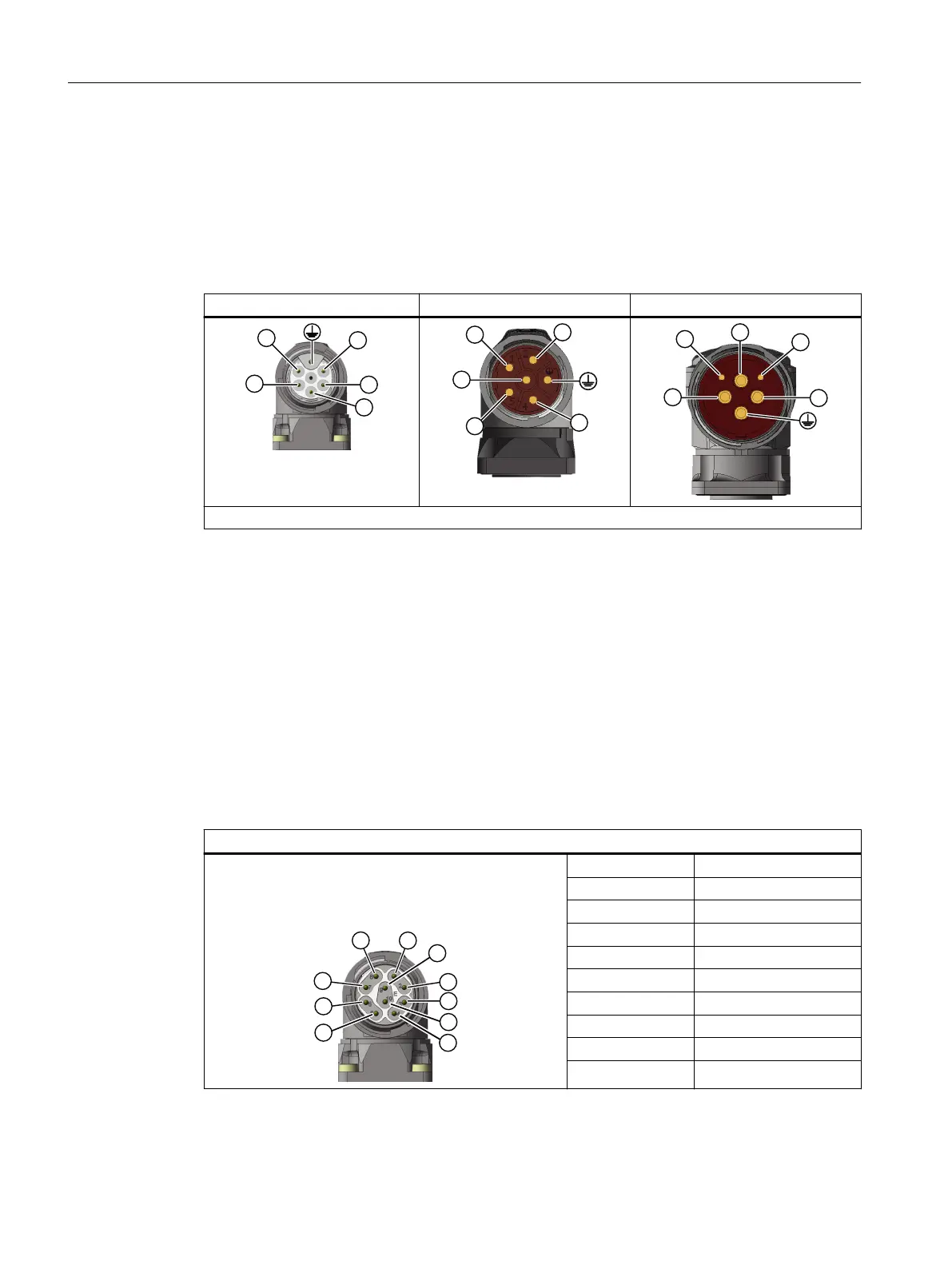
The 1F☐2 is equipped with the following power connectors depending on the frame size and
performance level.
Round connector M17 Round connector M23 Round connector M40
Brake connection 24 V: "+" = BD1+; "-" = BD2-
The power connectors can be rotated within a certain range.
More precise information about the equipping of the motors and the angles of rotation is
provided in Chapter "Rotating the connector on the motor (Page 70)".
6.3.3 Signal connection
Signal connector designs
The signal connection of the 1F☐2 is established using a round connector M17.
The connector pin assignment is as follows.
M17 signal connector, with DRIVE-CLiQ
1 TX-P
2 TX-N
3 -
4 -
5 RX-P
6 RX-N
7 -
8 -
9 24 V
10 0 V
The signal connector can be twisted in a certain range.
Connecting
6.3 System integration
SIMOTICS S-1FK2 synchronous motors for SINAMICS S120
72 Operating Instructions, 02/2022, A5E46089564B AD