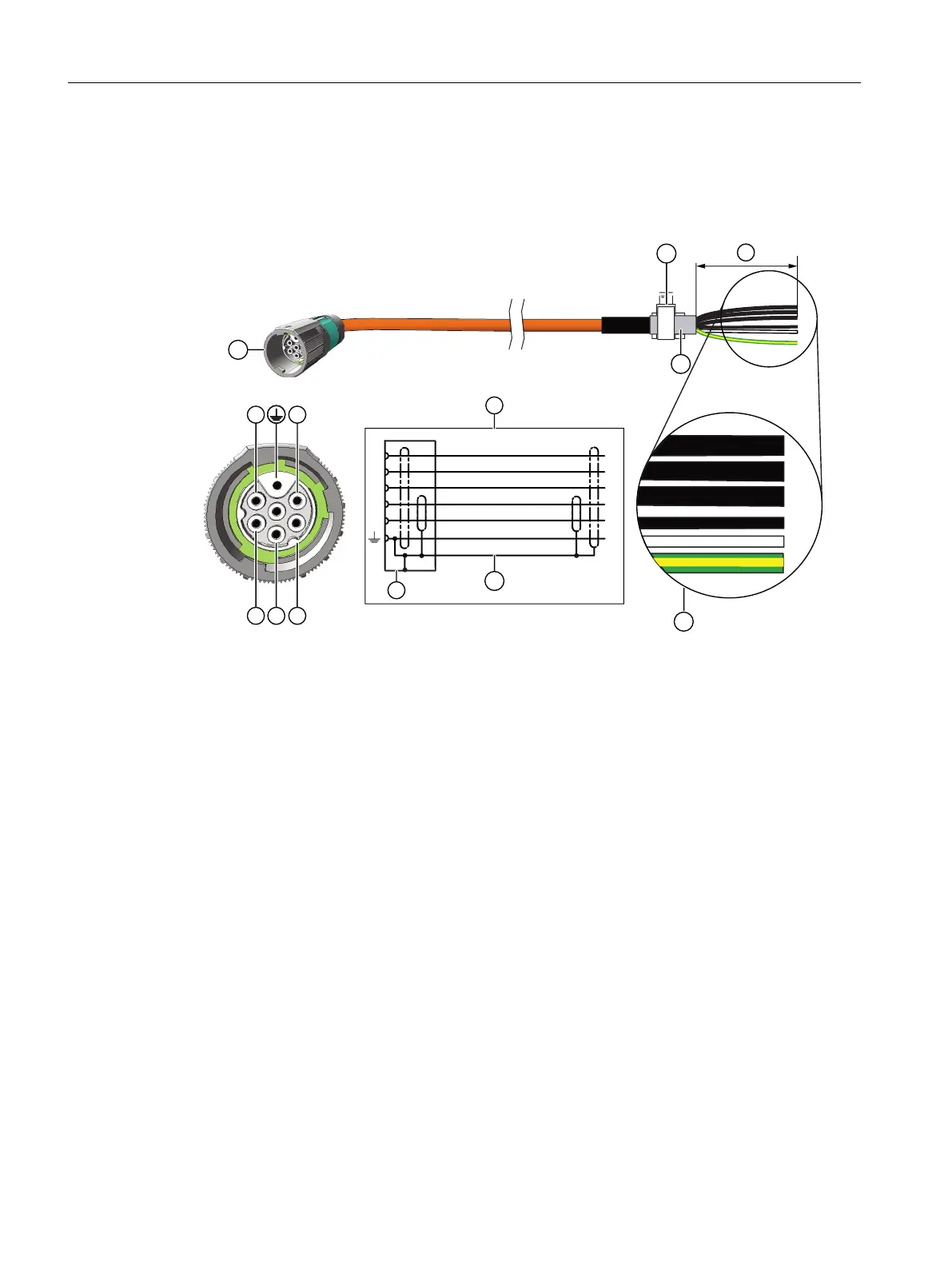
Connection diagram for the 1F☐2 motor to S120 with a MOTION-CONNECT line
For connector size M17
7
68
8-%-
7-
6-$-
7-
#%
(/:&
8)
#,
#,
#,
#,
#%
8-%-
1&
#3
8
7
6
6-$-
1 MOTION-CONNECT cable with SPEED CONNECT plug, size M17
2 Terminal for the cable shield
3 Cable shield
4 Connection diagram
U; V; W = power cables, 1.5 mm
2
, each cable with separate shielding
BD1+ and BD2- = brake cable without lettering, 1.5 mm
2
, shielded together
PE = protective conductor
5 Cable shield
6 Conductor designations
7 Recommended length of the cable ends: 105 mm
Connecting
6.3 System integration
SIMOTICS S-1FK2 synchronous motors for SINAMICS S120
74 Operating Instructions, 02/2022, A5E46089564B AD