LED displays
The
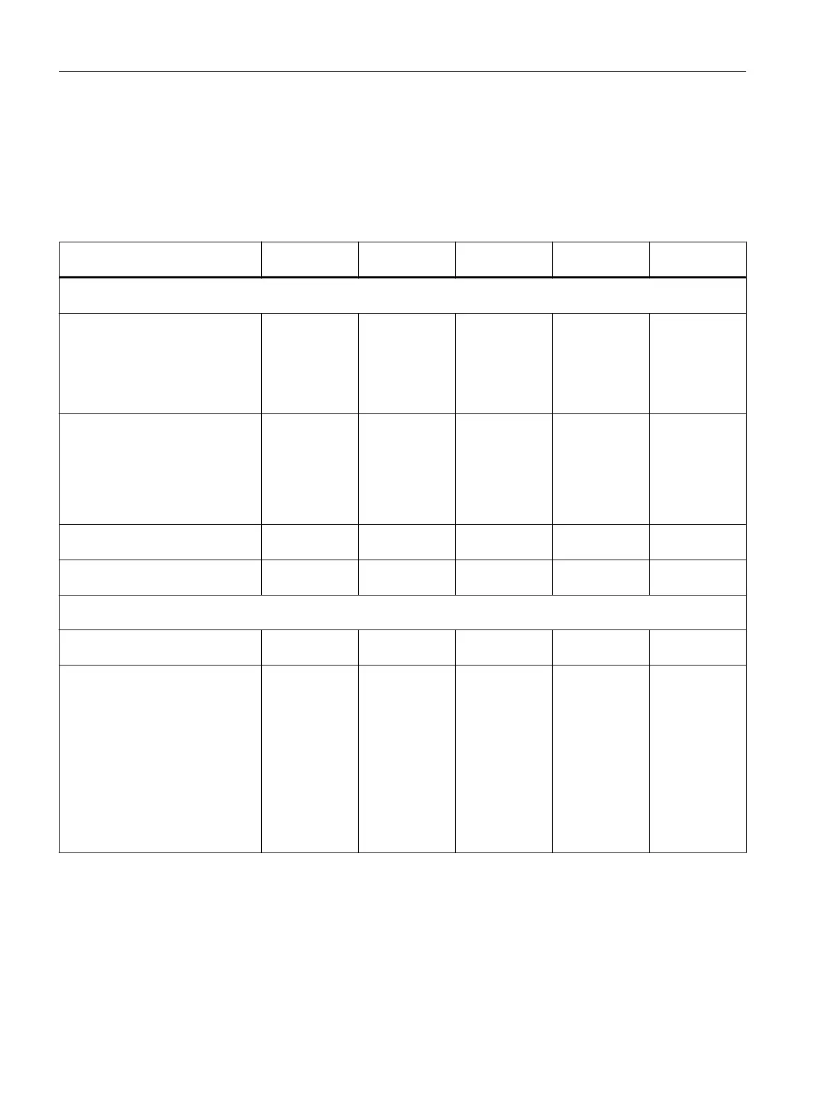
two tables below provide an overview of all relevant LED display combinations. Every LED
can illuminate in yellow, red, or green. The color which corresponds with the LED signal state
is also defined.
Table 9-2 SIMOTION D410‑2 DP and D410‑2 DP/PN: Diagnostics by means of LED display
Meaning Display priority
1)
RDY RUN/STOP OUT>5V
OUT>5V/SY
2)
SF/BF:
States during power-up
Hardware reset
Power-up of the D410‑2 without a
CF
card or power-up with a CF card
(CF card with incorrect / missing /
faulty boot loader or without a valid
operating system)
1 1
(yellow)
1
(yellow)
1
(yellow)
1
(yellow)
Firmware error
● No
or incorrect firmware on the
CF card
● File system of the CF card is
destroyed (e.g through power
off during writing operation)
x
3)
2/1
(red)
0 0 2/1
(red)
Firmware checked (checksum in‐
correct)
x
3)
0,5/1
(red)
0 0 0,5/1
(red)
Firmware being loaded x
3)
Λ
(yellow)
0 0 1
(red)
SIMOTION states
Write/read SIMOTION access to
CF card
1 Λ
(yellow)
x x x
"FAULT" state (F state)
Fault to which the user program
(SIMOTION) cannot respond (e.g.
overtemperature).
The following actions may be re‐
quired to rectify the fault:
●
Power OFF/ON
● Check of the CF card
● Re-commissioning
● Replace the SIMOTION D410-2
2 Λ
(red)
Λ
(red)
Λ
(red)
Λ
(red)
Diagnostics
9.1 Diagnostics via LED displays
SIMOTION D410-2
298 Commissioning and Hardware Installation Manual, 01/2015

 Loading...


