SINAMICS G130
Engineering Information
SINAMICS Engineering Manual – November 2015
Ó Siemens AG
280/528
Overload and overtemperature protection
SINAMICS G130 Chassis are equipped with effective overload and overtemperature protection mechanisms which
protect them against thermal overloading.
Sensors at various locations in the converter (inlet air, control electronics, rectifier heatsink, inverter heatsink)
measure the relevant temperatures and feed them into the so-called "Thermal model". This continuously calculates
the temperature at critical positions on power components. In this way the converter is effectively protected against
thermal overloads, whether they are caused by excessive current or high ambient temperatures. The so-called "I
2
t"
monitoring circuit checks the level of utilization of the motor-side inverter. If the level of inverter utilization or the
temperature at any point in the converter exceeds the upper tolerance limit, the converter responds by initiating an
overload reaction parameterized in the firmware. It is possible to select whether the converter should react to
overload by reducing the output frequency and output current or the pulse frequency. Immediate shutdown can also
be parameterized.
Maximum output frequency
With SINAMICS G130 Chassis units, the maximum output frequency is limited to 100 Hz or 160 Hz due to the
factory-set pulse frequency of f
Pulse
= 1.25 kHz (current controller clock cycle = 400 μs) or f
Pulse
= 2.00 kHz (current
controller clock cycle = 250 μs) The pulse frequency must be increased if higher output frequencies are to be
achieved. Since the switching losses in the motor-side IGBT inverter increase when the pulse frequency is raised, the
output current must be reduced accordingly.
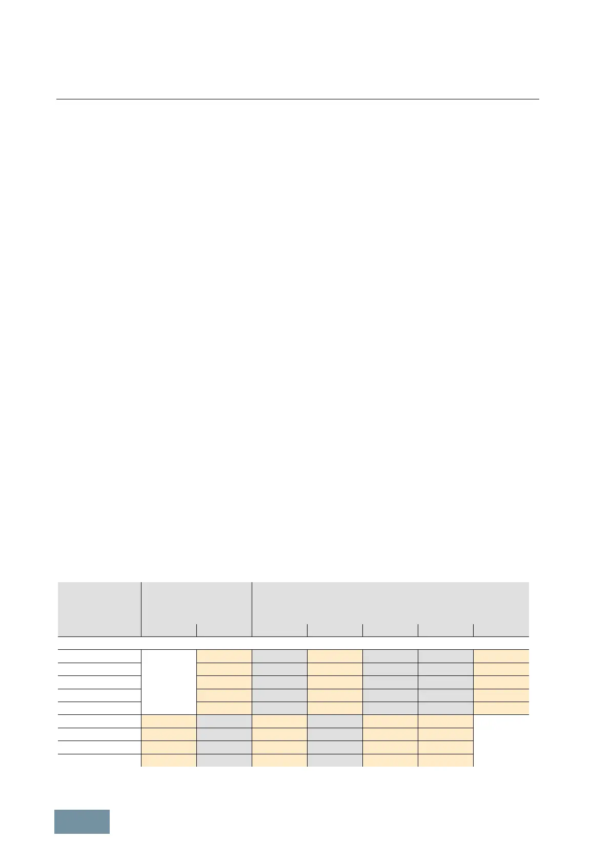
Permissible output current and maximum output frequency as a function of pulse frequency
The table below states the rated output currents of SINAMICS G130 converters with the factory-set pulse frequency,
as well as the current derating factors (permissible output currents referred to the rated output current) at higher
pulse frequencies.
The pulse frequencies for the values in the orange boxes can be selected simply by changing a parameter (even
during operation), i.e. they do not necessitate a change to the factory-set current controller clock cycle. The pulse
frequencies for the values in the grey boxes require a change in the factory-set current controller clock cycle and can
therefore be selected only at the commissioning stage. The assignment between current controller clock cycles and
possible pulse frequencies can be found in the List Manual (Parameter List).
Under certain boundary conditions (line voltage at low end of permissible wide-voltage range, low ambient
temperature, restricted speed range), it is possible to partially or completely avoid current derating at pulse
frequencies which are twice as high as the factory setting. Further details can be found in section "Operation of
converters at increased pulse frequency".
Output power
at
400V / 500V / 690 V
Rated output current
or
current derating factor
with pulse frequency of
Current derating factor
with pulse frequency of
1.25 kHz 2.0 kHz 2.5 kHz 4.0 kHz 5.0 kHz 7.5 kHz 8.0 kHz
380 V – 480 V 3AC
110 kW 210 A 95 % 82 % 74 % 54 % 50 %
132 kW 260 A 95 % 83 % 74 % 54 % 50 %
160 kW 310 A 97 % 88 % 78 % 54 % 50 %
200 kW 380 A 96 % 87 % 77 % 54 % 50 %
250 kW 490 A 94 % 78 % 71 % 53 % 50 %
315 kW 605 A 83 % 72 % 64 % 60 % 40 %
400 kW 745 A 83 % 72 % 64 % 60 % 40 %
450 kW 840 A 87 % 79 % 64 % 55 % 40 %
560 kW 985 A 92 % 87 % 70 % 60 % 50 %
SINAMICS G130: Permissible output current (current derating factor) as a function of pulse frequency

 Loading...


