With cutting edge position compensation (CUTMOD) for turning and grinding tools, the
cutting plane for calculating the compensation values is rotated into the machining
plane. If this
bit is not set, the cutting edge is projected into the machining plane
instead.
Bit18:
With cutting edge position compensation (CUTMOD) for turning and grinding tools,
always use the active plane (G17 - G19). If this bit is not set, the plane specified
by
setting data
SD42940 $SC_TOOL_LENGTH_CONST has priority over the plane specified by
the G code group 6 (plane selection, G17 - G19).
Bit19:
The tool orientation change caused by an orientable tool holder becomes effective even
if no tool is active. This bit is only effective if bit 10 is also set.
Bit20:
If this bit is zero, and if the tool parameter $TC_DP10 (holder angle) and/or $TC_DP24
(clearance angle) contain the value 0, the following default values are used as the
basis
for the
function CUTMOD to calculate the modified cutting-edge position and the
modified cutting-edge direction:
Holder angle 112.5 degrees for cutting-edge positions 1 - 4
Holder angle 67.5 degrees for cutting-edge positions 5 - 8
Clearance angle 22.5 degrees for cutting edge positions 1 - 4
Clearance angle 67.5 degrees for cutting-edge positions 5 - 8
If this bit is set, an alarm is output in the cases mentioned. This bit is used to
establish compatibility with older software releases.
Bit21:
If this bit is zero, any existing rotation in the part proportion of the tool carrier
is taken into account for CUTMOD with tool carrier when modifying the cutting edge
position. Frames are ignored.
If this bit is 1, in the place of the part proportion of the tool carrier, the
active total frame is taken into account with CUTMOD with tool carrier with
modification of the cutting edge position. The total frame can also contain a part
proportion of the tool carrier.
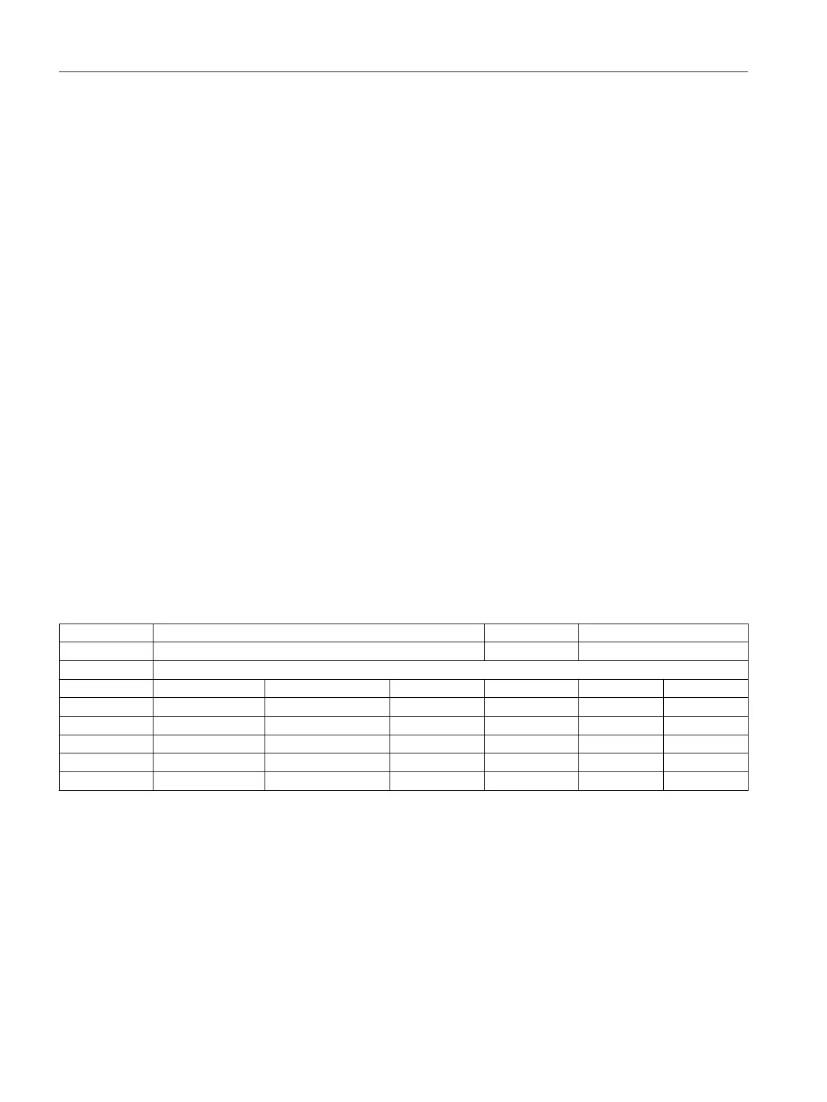
20380 TOOL_CORR_MODE_G43G44 C01, C08, C11 -
- Treatment of tool length compensation with G43 / G44 BYTE Reset
-
808d-me42 - 1 0 2 2/2 M
808d-me62 - 1 0 2 2/2 M
808d-te42 - 0, 0, 0, 0, 0, 0, 0, 0... 0 2 2/2 M
808d-te62 - 0, 0, 0, 0, 0, 0, 0, 0... 0 2 2/2 M
808d-mte40 - 0, 0, 0, 0, 0, 0, 0, 0... 0 2 2/2 M
808d-mte60 - 0, 0, 0, 0, 0, 0, 0, 0... 0 2 2/2 M
Description: This machine data determines in ISO dialect M (G43 / G44) the way in which length
compensations programmed with H are processed.
0: Mode A
Tool length H always acts on the third geometry axis (usually Z)
1: Mode B
Tool length H acts, depending on the active plane, on one of the three geometry axes.
This means with
G17 on the 3rd geometry axis (usually Z)
G18 on the 2nd geometry axis (usually Y)
G19 on the 1st geometry axis (usually X)
Machine data
3.3 Channel-specific machine data
Parameter Manual
144 Parameter Manual, 08/2015, 6FC5397-8EP40-0BA1
 Loading...


