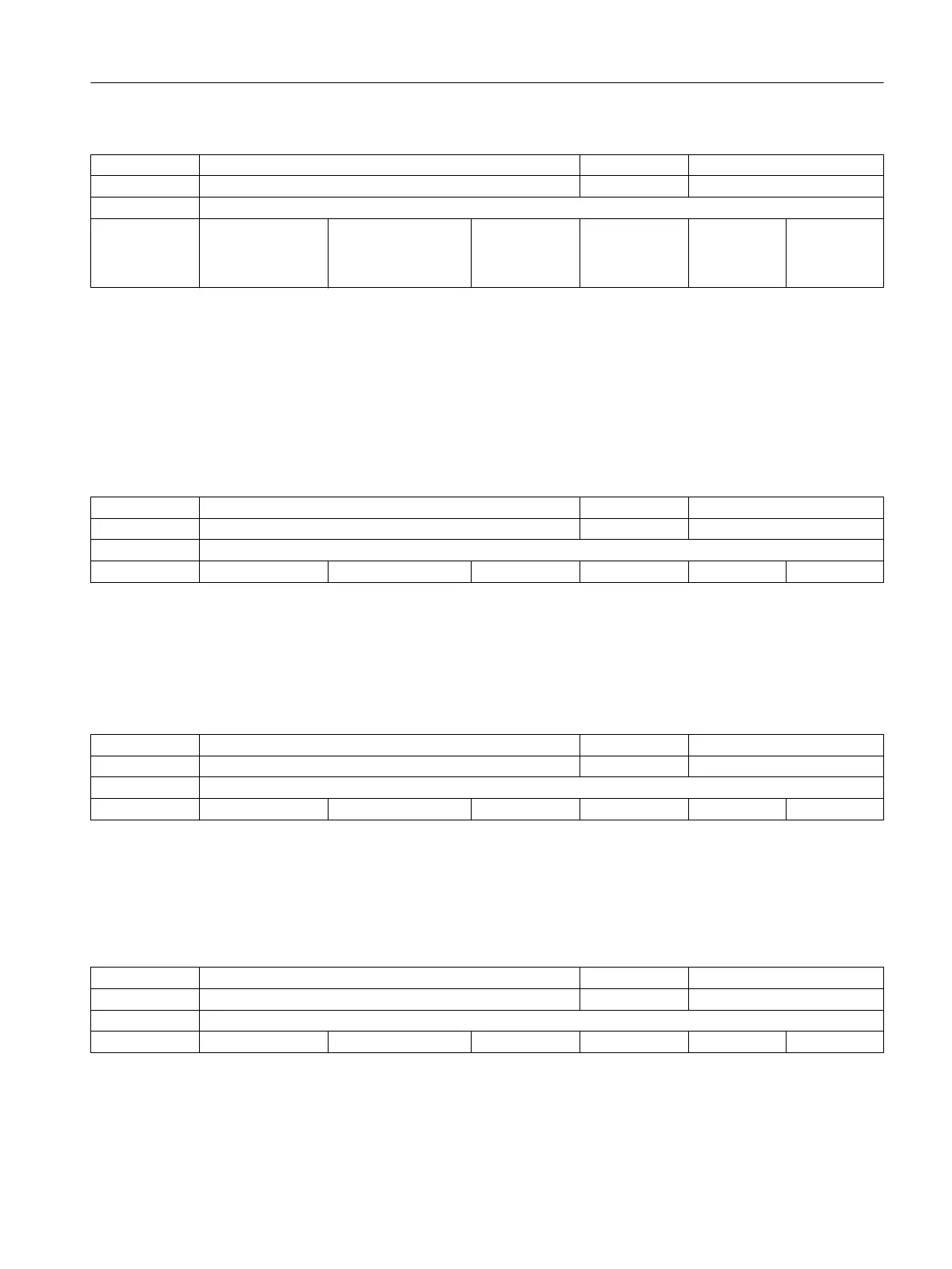
22410 F_VALUES_ACTIVE_AFTER_RESET C04, C03, C05 M3, V1
- F function active beyond RESET BOOLEAN PowerOn
-
- - FALSE, FALSE,
FALSE, FALSE,
FALSE, FALSE,
FALSE, FALSE...
0 - 2/2 M
Description: 1: The last programmed F, FA, OVR and OVRA values are still active after RESET.
This also applies to the dynamic correction values (ACC, VELOLIM, JERKLIM, ACCLIMA,
VELOLIMA, JERKLIMA).
0: The various values are set to their default values after reset.
This does not apply to the dynamic correction values if the axis-specific MD32320
$MA_DYN_LIMIT_RESET_MASK specifies anything else.
Note:
The dynamic correction values are also retained if the axis-specific MD32320
$MA_DYN_LIMIT_RESET_MASK is not equal to zero.
Related to:
22510 GCODE_GROUPS_TO_PLC C04 K1, P3 pl, P3 sl
- G codes output at NCK-PLC interface on block change/RESET BYTE PowerOn
-
- 8 2, 0, 0, 0, 0, 0, 0, 0 - - 1/1 M
Description: Specification of the G code group, the G codes of which are output to the NCK/PLC
interface in case of block change/ reset.
The interface is updated after each block change and reset.
Notice:
It is not guaranteed that a PLC user program has at all times a block-synchronous
relation between the active NC block and the G codes present.
Example: Path mode with very short blocks
22512 EXTERN_GCODE_GROUPS_TO_PLC C11, C04 -
- Send G codes of an external NC language to PLC BYTE PowerOn
-
- 8 18, 0, 0, 0, 0, 0, 0, 0 - - 1/1 M
Description: Specification of the G code group of external languages, the G codes of which are
output at the NCK interface on block change/reset.
The interface is updated at each block change and after RESET.
Notice:
It is not guaranteed that a PLC user program has at all times a block-synchronous
relation
between the
active NC block and the G codes present. (Example: Path mode with
very short blocks).
22515 GCODE_GROUPS_TO_PLC_MODE C04 -
- Behavior of G group transfer to PLC DWORD PowerOn
-
- - 0, 0, 0, 0, 0, 0, 0, 0... 0 0x1 1/1 M
Description: For setting the behavior, i.e. how the G groups are to be interpreted in the PLC with
regard to data.
With the current behavior (bit 0 = 0), the G group is the array index of a 64-byte
field (DBB 208 - DBB 271).
Maximally the 64th G group can be reached in this way.
Machine data
3.3 Channel-specific machine data
Parameter Manual
Parameter Manual, 08/2015, 6FC5397-8EP40-0BA1 171

 Loading...


