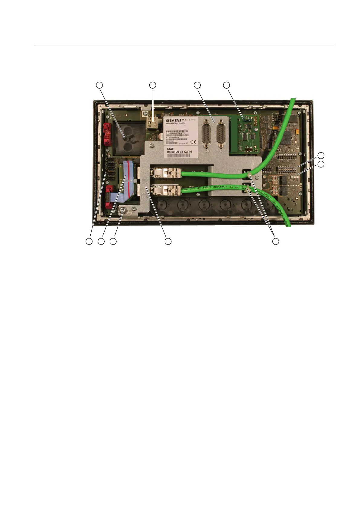
① Slot for Emergency-Stop button or spindle override
② Power supply interface X10
③ X60 connection for handwheel, X61 reserved
④ Switch for setting the handwheel signal type
⑤ Switch S2
⑥ LEDs
⑦ Ethernet cable strain relief
⑧ PLC I/O Interface connections X20 (port 1), X21 (port 2) behind cover plate
⑨ Equipotential bonding
⑩ Feed override
⑪ Customer-specific inputs and outputs
Figure 7-13 Rear of the MCP 310C PN with Ethernet connecting cables
Equipotential bonding
The equipotential bonding conductor is attached by means of an M5 screw.
Connectable components
7.2 MCP 310C PN
PPU
Manual, 01/2014, 6FC5397-2DP40-3BA3 115

 Loading...


