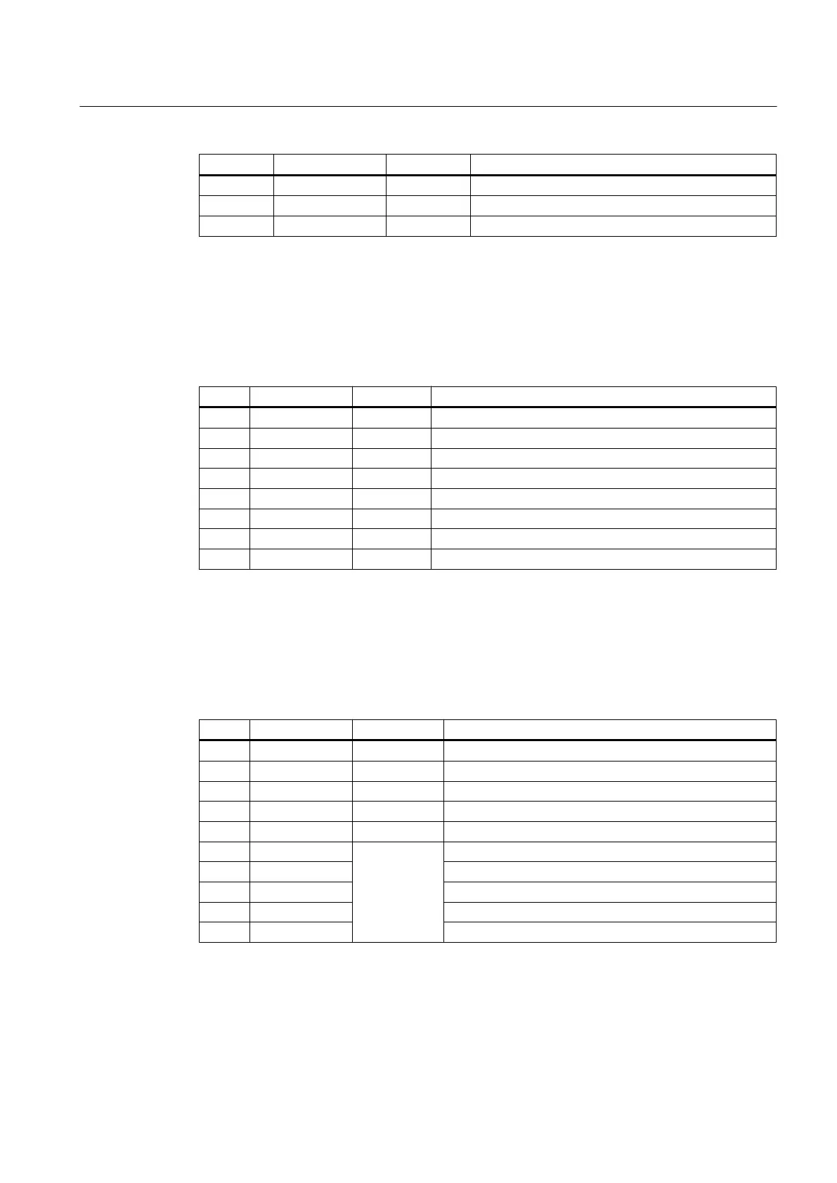
Pin Signal name Signal type Meaning
1 P24 V 24 V potential
2 M24 V 24 V ground
3 SHIELD V Shield connection
PLC I/O Interface pin assignment
Connector designation: X20, X21
Connector type: RJ45 socket
Table 7-18 Assignment of connectors X20, X21
Pin Signal name Signal type Meaning
1 TX+ I Transmit +
2 TX- I Transmit -
3 RX+ O Receive +
4 N.C. - Not assigned
5 N.C. - Not assigned
6 RX- O Receive -
7 N.C. - Not assigned
8 N.C. - Not assigned
Rotary switch: Feed override X30 / spindle override X31
Connector designation: X30/X31
Connector type: 2 x 5-pin plug connector, according to EN 60603-13 with coding
Table 7-19 Assignment of connector X30
Pin Signal name Signal type Meaning
1 N.C. - Not assigned
2 N.C. - Not assigned
3 M V Ground
4 N.C. - Not assigned
5 P5 V 5 V supply
6 OV16
I
Rotary override switch, position/value 16
7 OV8 Rotary override switch, position/value 8
8 OV4 Rotary override switch, position/value 4
9 OV2 Rotary override switch, position/value 2
10 OV1 Rotary override switch, position/value 1
Connectable components
7.2 MCP 310C PN
PPU
Manual, 01/2014, 6FC5397-2DP40-3BA3 119

 Loading...


