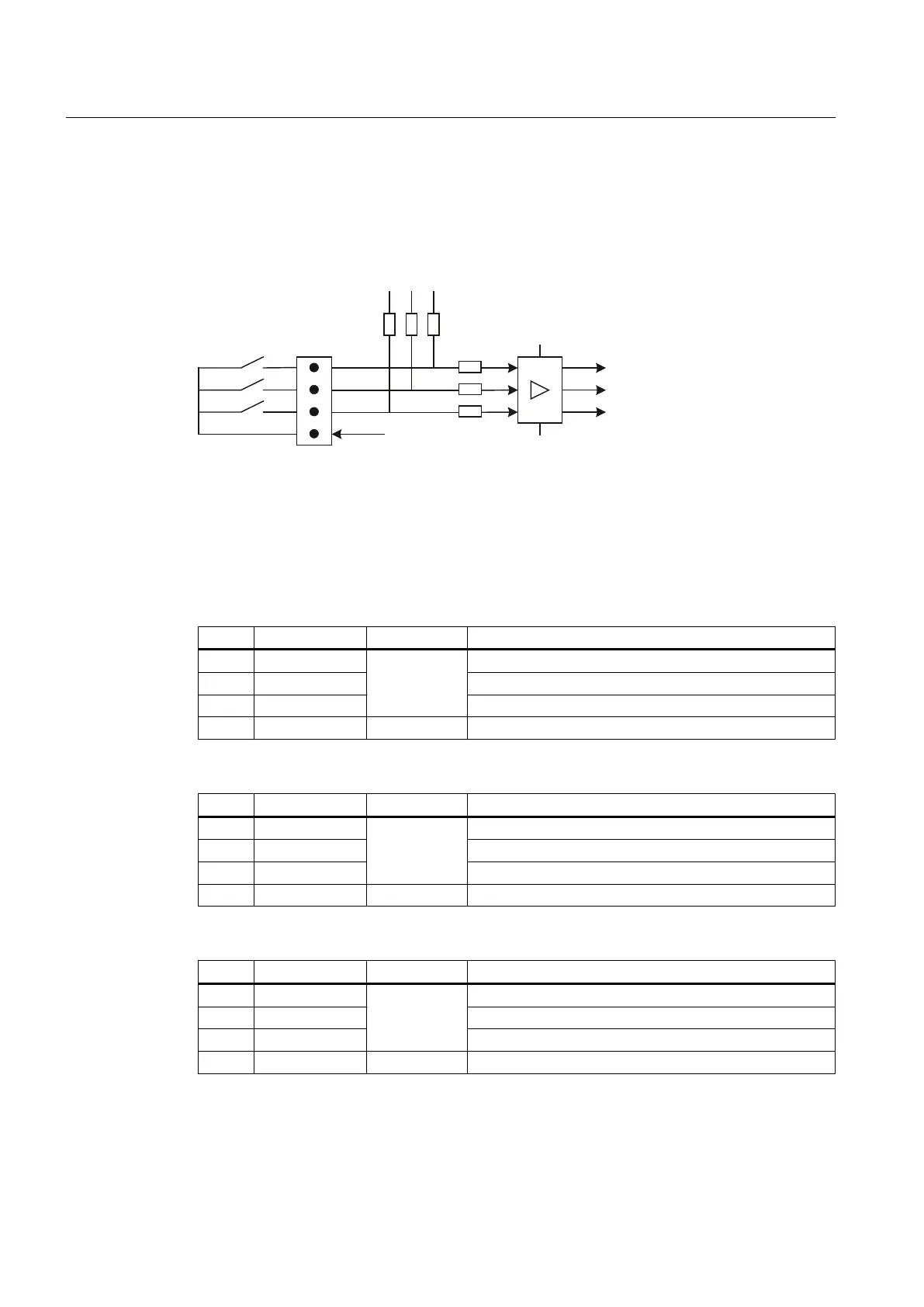
Optional customer buttons IN (X51 / X52 / X55)
Only switches (passive inputs) may be connected via the X51, X52 and X55 connectors. X51
and X52 are typically used for connecting illuminated pushbuttons. The lamps in the buttons
are activated via X53 and X54. X55 has no corresponding outputs.
;L
0
0
.7M,1
.7M,1
.7M,1
9
.
9
L
M
.
Figure 7-16 Main circuit diagram for input circuit for X51, X52 and X55
Connector designation: X51, X52, X55
Connector type: 4-pin plug connector
Table 7-20 Assignment of connector X51
Pin Signal name Signal type Meaning
1 KT-IN1
I
Customer key 1
2 KT-IN2 Customer key 2
3 KT-IN3 Customer key 3
4 M V Ground
Table 7-21 Assignment of connector X52
Pin Signal name Signal type Meaning
1 KT-IN4
I
Customer key 4
2 KT-IN5 Customer key 5
3 KT-IN6 Customer key 6
4 M V Ground
Table 7-22 Assignment of connector X55
Pin Signal name Signal type Meaning
1 KT-IN7
I
Customer key 7
2 KT-IN8 Customer key 8
3 KT-IN9 Customer key 9
4 M V Ground
Connectable components
7.2 MCP 310C PN
PPU
120 Manual, 01/2014, 6FC5397-2DP40-3BA3

 Loading...


