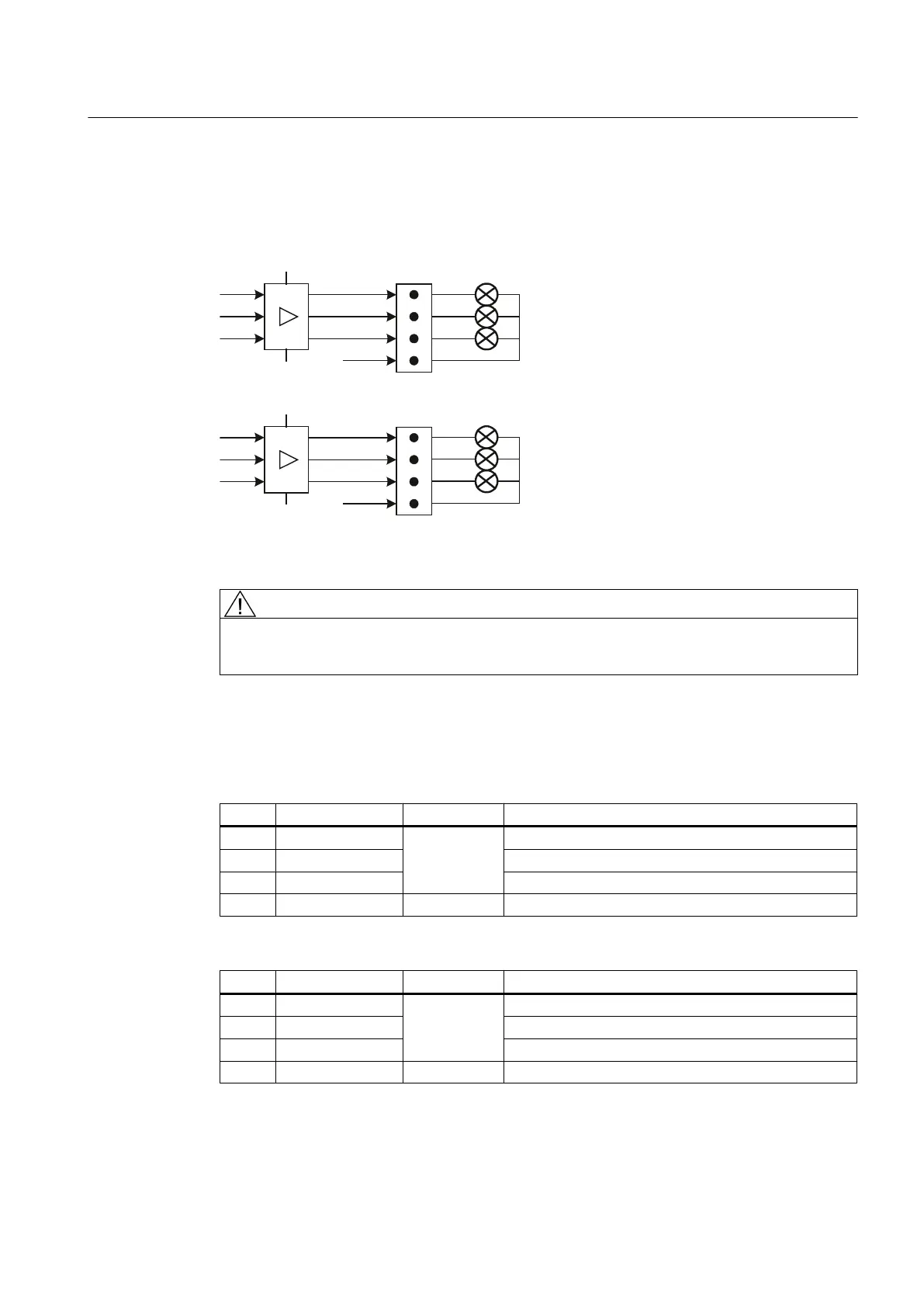
Optional customer buttons OUT (X53 / X54)
The short-circuit-proof outputs X53/X54 are provided to control lamps in the buttons. Lamps
with 24 V and 1.2 W per output are recommended.
;
0
0
3
.7287
.7287
.7287
;
0
0
3
.7287
.7287
.7287
Figure 7-17 Main circuit diagram for input circuit for X53 and X54
CAUTION
Do not connect any relays, valves or other inductive loads.
Connector designation: X53, X54
Connector type: 4-pin plug connector
Table 7-23 Assignment of connector X53
Pin Signal name Signal type Meaning
1 KT-OUT1
O
Output 1 lamp
2 KT- OUT2 Output 2 lamp
3 KT- OUT3 Output 3 lamp
4 M V Ground
Table 7-24 Assignment of connector X54
Pin Signal name Signal type Meaning
1 KT-OUT4
O
Output 4 lamp
2 KT- OUT5 Output 5 lamp
3 KT- OUT6 Output 6 lamp
4 M V Ground
Connectable components
7.2 MCP 310C PN
PPU
Manual, 01/2014, 6FC5397-2DP40-3BA3 121

 Loading...


