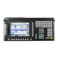
Table 7-60 Coding of axis selection switch
Connector X1
Switch position Function
Pin 8 Pin 9 Pin 10
0 0 0 - Mini HHU not connected
1 1 0 0 No axis selected
0 1 0 Z Z axis selected
0 1 1 X X axis selected
1 1 1 Y Y axis selected
1 0 1 4 Axis 4 selected
0 0 1 5 Axis 5 selected
● Enabling button
The enabling button is designed as a 3-way switch. This must be held in its central position
for movements to be triggered.
● Handwheel
The handwheel can be used to initiate movements at the selected axis using the axis
selection switch.
● Rapid traverse key
The rapid traverse key increases the traversing speed of the selected axis with the axis
selector switch. The rapid traverse button is active both for traversing commands issued
via the +/- keys and for handwheel signals.
● Traversing keys
The + and - traversing keys can be used to trigger traversing movements on the axis
selected via the axis selection switch.
● Function keys
The function keys can be used to trigger machine-specific functions.
Connectable components
7.5 Mini handheld unit
PPU
156 Manual, 01/2014, 6FC5397-2DP40-3BA3

 Loading...


