12.95
2.1 Secondary electrical conditions
2-28
E Siemens AG, 2002. All rights reserved
SINUMERIK 810D Manual Hardware Configuration (PHC) -- 11.02 Edition
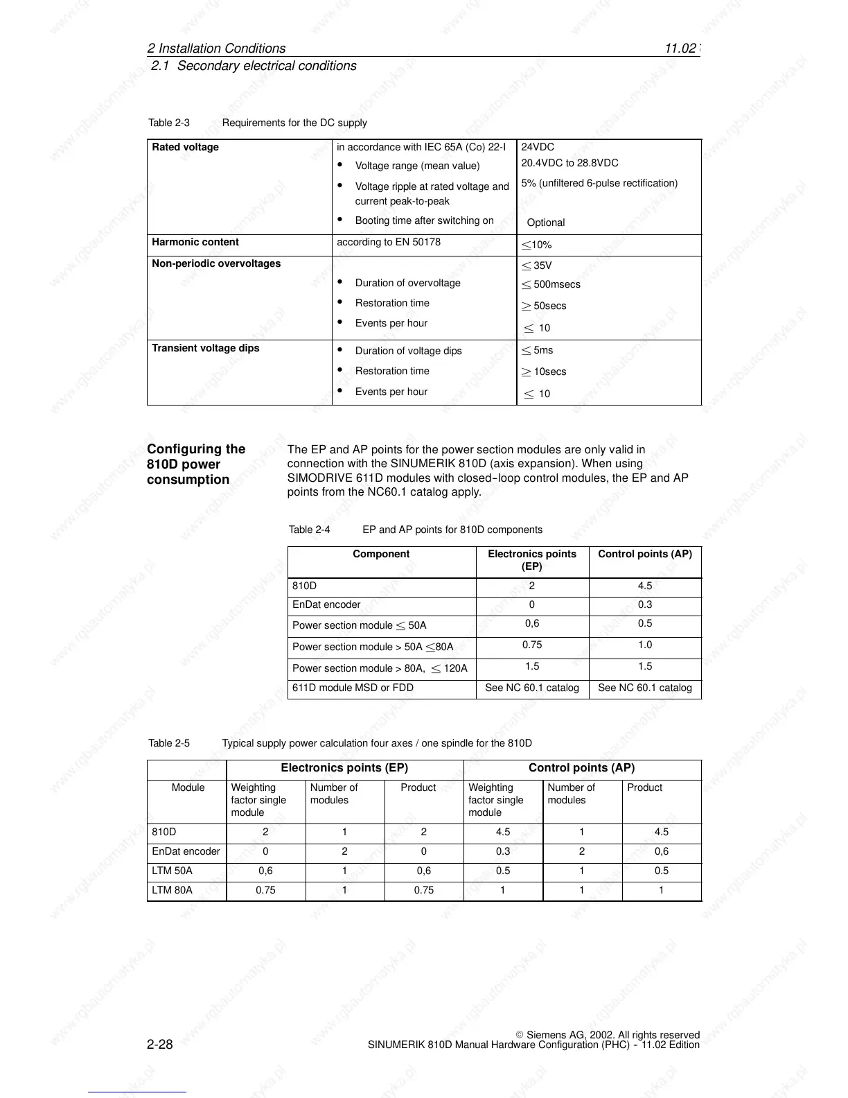
Table 2-3 Requirements for the DC supply
Rated voltage
in accordance with IEC 65A (Co) 22-I
S Voltage range (mean value)
S Voltage ripple at rated voltage and
current peak-to-peak
S Booting time after switching on
24VDC
20.4VDC to 28.8VDC
5% (unfiltered 6-pulse rectification)
Optional
Harmonic content according to EN 50178
±10%
Non-periodic overvoltages
S Duration of overvoltage
S Restoration time
S Events per hour
± 35V
± 500msecs
² 50secs
± 10
Transient voltage dips
S Duration of voltage dips
S Restoration time
S Events per hour
± 5ms
² 10secs
± 10
The EP and AP points for the power section modules are only valid in
connection with the SINUMERIK 810D (axis expansion). When using
SIMODRIVE 611D modules with closed--loop control modules, the EP and AP
points from the NC60.1 c atalog apply.
Table 2-4 EP and AP points for 810D components
Component
Electronics points
(EP)
Control points (AP)
810D 2 4.5
EnDat encoder 0 0.3
Power section module ± 50A
0,6 0.5
Power section module > 50A ±80A
0.75 1.0
Power section module > 80A, ± 120A
1.5 1.5
611D module MSD or FDD See NC 60.1 catalog See NC 60.1 catalog
Table 2-5 Typical supply power calculation four axes / one spindle for the 810D
Electronics points (EP) Control points (AP)
Module Weighting
factor single
module
Number of
modules
Product Weighting
factor single
module
Number of
modules
Product
810D
2
1 2 4.5 1 4.5
EnDat encoder 0 2 0 0.3 2 0,6
LTM 50A 0,6 1 0,6 0.5 1 0.5
LTM 80A 0.75 1 0.75 1 1 1
Configuring the
810D power
consumption
2In
 Loading...


