12.95
4.2 Interfaces of the SINUMERIK 810D
4-56
E Siemens AG, 2002. All rights reserved
SINUMERIK 810D Manual Hardware Configuration (PHC) -- 11.02 Edition
4.2.3 CCU1/CCU2: Description of the in t erfaces, o perating an d display
elements
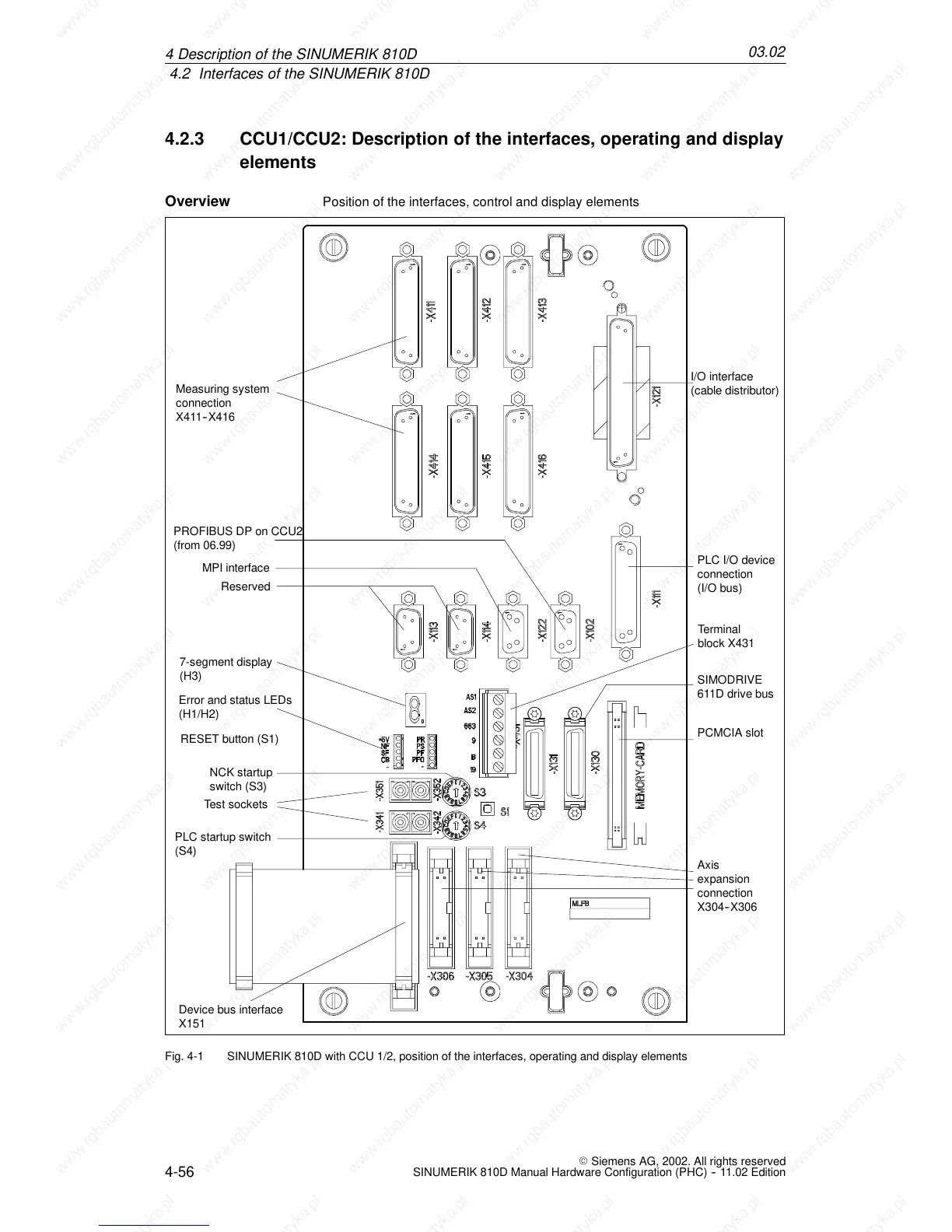
Position of the interfaces, control and display elements
Reserved
PLC I/O device
connection
(I/O bus)
MPI interface
I/O interface
(cable distributor)
Error and status LEDs
(H1/H2)
7-segment display
(H3)
RESET button (S1)
PLC startup switch
(S4)
NCK s tartup
switch (S3)
SIMODRIVE
611D drive bus
PCMCIA slot
Device bus interface
X151
Axis
expansion
connection
X304--X306
Test sockets
Measuring system
connection
X411--X416
Terminal
block X431
PROFIBUS DP on CCU2
(from 06.99)
Fig. 4-1 SINUMERIK 810D with CCU 1/2, position of the interfaces, operating and display elements
Overview
4De
 Loading...


