12.95
2.3 Technical data of the individual components
2-37
E Siemens AG, 2002. All rights reserved
SINUMERIK 810D Manual Hardware Configuration (PHC) -- 11.02 Edition
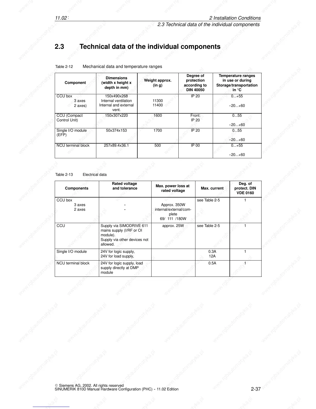
2.3 Technical data of the individual components
Table 2-12 Mechanical data and temperature ranges
Component
Dimensions
(width x height x
depth in mm)
We ight approx.
(in g)
Degree of
protection
according to
DIN 40050
Temperature ranges
in use or during
Storage/transportation
in C
CCU box
3axes
2 axes)
150x490x268
Internal ventilation
Internal and external
vent.
11300
11400
IP 20 0...+55
--20...+60
CCU (Compact
Control Unit)
150x307x220 1600 Front:
IP 20
0...55
--20...+60
Single I/O module
(EFP)
50x374x153 1700 IP 20 0...55
--20...+60
NCU terminal block 257x89.4x36.1 500 IP 00 0...+55
--20...+60
Table 2-13 Electrical data
Components
Rated voltage
and tolerance
Max. power loss at
rated voltage
Max. current
Deg. of
protect. DIN
VDE 0160
CCU box
3axes
2axes
--
--
Approx. 350W
internal/external/com-
plete
69/ 111 /180W
seeTable2-5 1
CCU Supply via SIMODRIVE 61 1
mains supply (I/RF or OI
module).
Supply via other devices not
allowed.
approx. 25W seeTable2-5 1
Single I/O module 24V for logic supply,
24V for load supply,
0.3A
12A
1
NCU terminal block 24V for logic supply , load
supply directly at DMP
module
0.5A 1
2In
 Loading...


