12.95
4.3 Measuring system
4-70
E Siemens AG, 2002. All rights reserved
SINUMERIK 810D Manual Hardware Configuration (PHC) -- 11.02 Edition
4.3.2 Evaluative enco d er systems
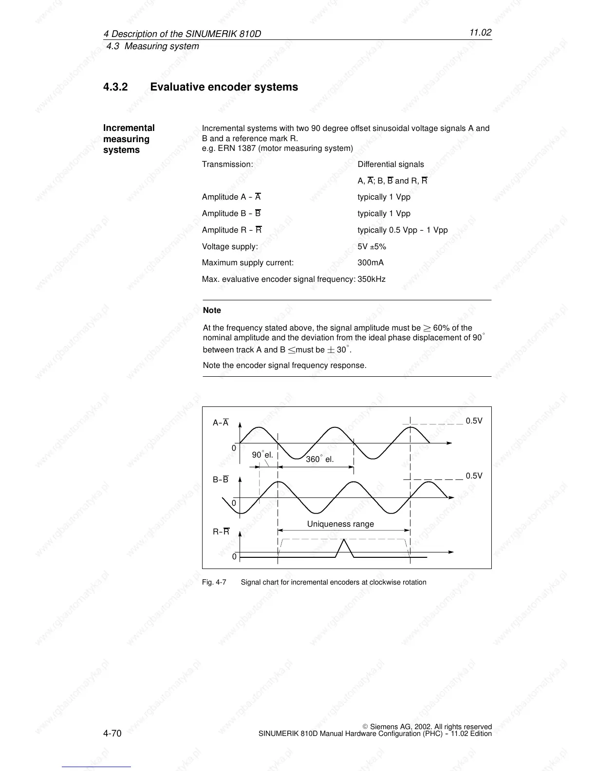
Incremental systems with two 90 degree offset sinusoidal voltage signals A and
B and a reference mark R.
e.g. ERN 1387 (motor measuring system)
Transmission: Differential signals
A, A
;B,Band R, R
Amplitude A -- A
typically 1 Vpp
Amplitude B -- B
typically 1 Vpp
Amplitude R -- R
typically 0.5 Vpp -- 1 Vpp
Voltage supply: 5V 5%
Maximum supply current: 300mA
Max. evaluative encoder signal frequency: 350kHz
Note
At the frequency stated above, the signal amplitude must be ² 60% of the
nominal amplitude and the deviation from the ideal phase displacement of 90
_
between track A and B ±mus t b e ¦ 30
_
.
Note the encoder signal frequency response.
A-- A
B-- B
R--
R
0
0
0
90
_
el.
360
_
el.
Uniqueness range
0.5V
0.5V
Fig. 4-7 Signal chart for incremental encoders at clockwise rotation
Incremental
measuring
systems
4De
 Loading...


