12.95
4.3 Measuring system
4-71
E Siemens AG, 2002. All rights reserved
SINUMERIK 810D Manual Hardware Configuration (PHC) -- 11.02 Edition
Singleturn, multiturn and linear absolute measuring systems with two 90
0
degree offset sinusoidal voltage signals A and B and an EnDat interface.
e.g. multiturn encoder EQN 1325, singleturn encoder ECN 1313 or linear abso-
lute measuring system LC181.
Transmission of incremental signals: Differential signals
A, A
and B, B
Amplitude A -- A
typically 1 Vpp
Amplitude B -- B typically 1 Vpp
Transmission of serial signals: Differential signals
data, data
and clock, clock
Level: Acc. to EIA 485
Voltage supply: 5V 5%
Maximum supply current: 300mA
Max. evaluative encoder signal frequency: 350kHz
Note
At the frequency stated above, the signal amplitude must be
² 60% of the
nominal amplitude and the deviation from the ideal phase displacement of 90 _
between track A and B
± must b e ¦ 30_.
Note the encoder signal frequency response.
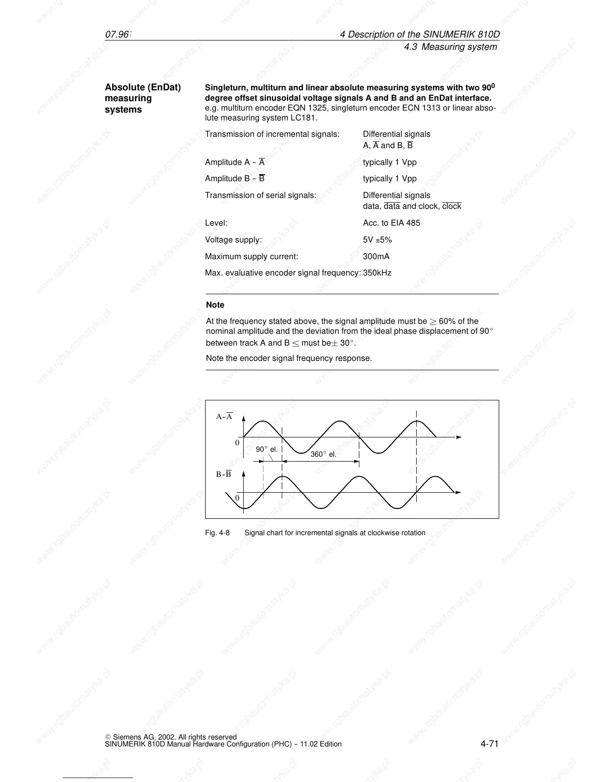
A--A
B--B
0
0
90_ el.
360
_ el.
Fig. 4-8 Signal chart for incremental signals at clockwise rotation
Absolute (EnDat)
measuring
systems
4De
 Loading...


