12.95
2.1 Secondary electrical conditions
2-29
E Siemens AG, 2002. All rights reserved
SINUMERIK 810D Manual Hardware Configuration (PHC) -- 11.02 Edition
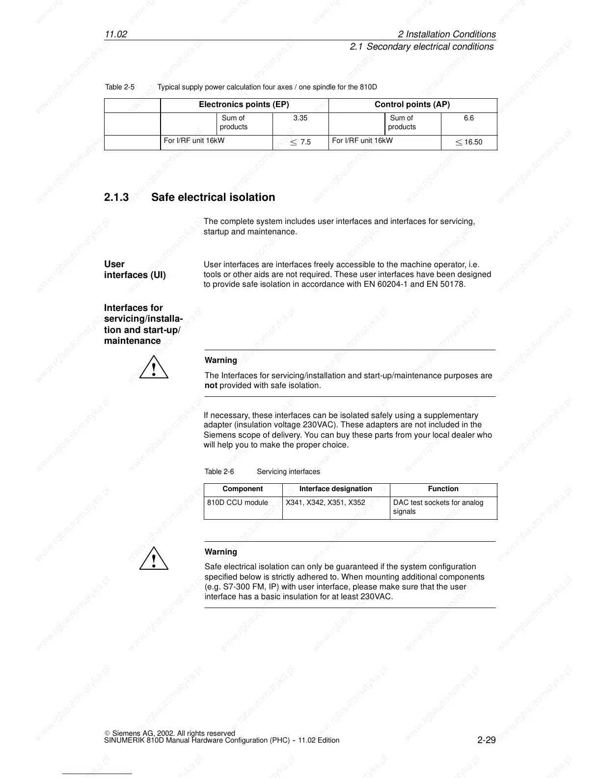
Table 2-5 Typical supply power calculation four axes / one spindle for the 810D
Control points (AP)Electronics points (EP)
Sum of
products
3.35 Sum of
products
6.6
For I/RF unit 16kW
± 7.5
For I/RF unit 16kW
± 16.50
2.1.3 Safe electrical iso latio n
The complete system includes user interfaces and interfaces for servicing,
startup and maintenance.
User interfaces are interfaces freely accessible to the machine operator, i.e.
tools or other aids are not required. These user interfaces have been designed
to provide safe isolation in accordance with EN 60204-1 and EN 50178.
!
Warning
The Interfaces for servicing/installation and start-up/maintenance purposes are
not provided with safe isolation.
If necessary, these interfaces can be isolated safely using a supplementary
adapter (insulation voltage 230VAC). These adapters are not included in the
Siemens scope of delivery. You can buy these parts from your local dealer who
will help you to make the proper choice.
Table 2-6 Servicing interfaces
Component
Interface designation Function
810D CCU module X341, X342, X351, X352 DAC test sockets for analog
signals
!
Warning
Safe electrical isolation can only be guaranteed if the system configuration
specified below is strictly adhered to. When mounting additional components
(e.g. S7-300 FM, IP) with user interface, please make sure that the user
interface has a basic insulation for at least 230VAC.
User
interfaces (UI)
Interfaces for
servicing/installa-
tion and start -up/
maintenance
2In
 Loading...


