12.95
2.1 Secondary electrical conditions
2-30
E Siemens AG, 2002. All rights reserved
SINUMERIK 810D Manual Hardware Configuration (PHC) -- 11.02 Edition
.
Basic insulation Safe isolation
M
3 x 400VAC
MP
Housing/shield
810D / 611D
1
2
3
4
10
4
4
5
6
11
S7-300 I/Os
MCP
PCU
9
24V
8
Human
M
7
10
11
Terminal
block
11
Machine
5
4
HHU
Distributor box
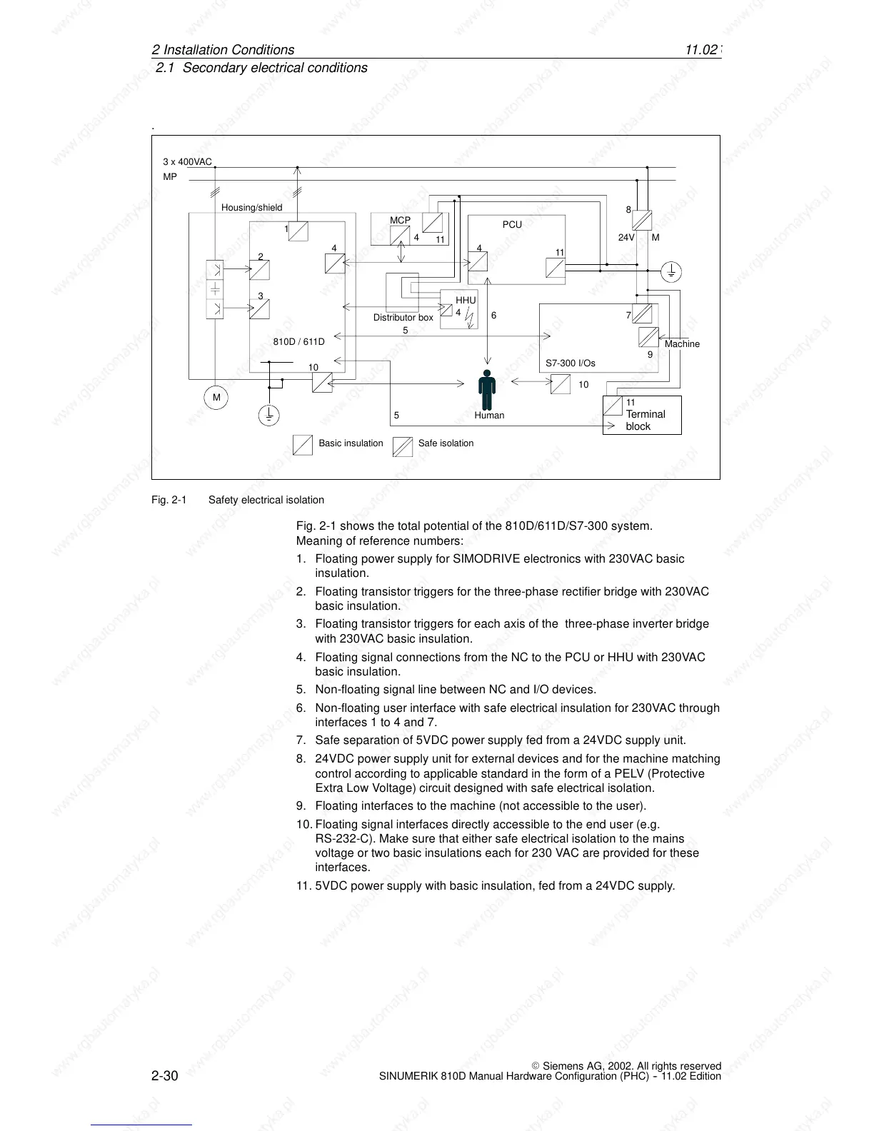
Fig. 2-1 Safety electrical isolation
Fig. 2-1 shows the total potential of the 810D/611D/S7-300 system.
Meaning of reference numbers:
1. Floating power supply for SIMODRIVE electronics with 230VAC basic
insulation.
2. Floating transistor triggers for the three-phase rectifier bridge with 230VAC
basic insulation.
3. Floating transistor triggers for each axis of the three-phase inverter bridge
with 230VAC basic insulation.
4. Floating signal connections from the NC to the PCU or HHU with 230VAC
basic insulation.
5. Non-floating signal line between NC and I/O devices.
6. Non-floating user interface with safe electrical insulation for 230VAC through
interfaces 1 to 4 and 7.
7. Safe separation of 5VDC power supply fed from a 24VDC supply unit.
8. 24VDC power supply unit for external devices and for the machine matching
control according to applicable standard in the form of a PELV (Protective
Extra Low Voltage) circuit designed with safe electrical isolation.
9. Floating interfaces to the machine (not accessible to the user).
10.Floating signal interfaces directly accessible to the end user (e.g.
RS-232-C). Make sure that either safe electrical isolation to the mains
voltage or two basic insulations each for 230 VAC are provided for these
interfaces.
11. 5VDC power supply with basic insulation, fed from a 24VDC supply.
2In
 Loading...


