12.95
4.2 Interfaces of the SINUMERIK 810D
4-65
E Siemens AG, 2002. All rights reserved
SINUMERIK 810D Manual Hardware Configuration (PHC) -- 11.02 Edition
The interfaces, operating and display elements of the CCU3 are the same as on
the CCU1/2 (see Subsection 4.2.3 with the following differences:
Additional pulse interface (axis 3)
Connector designation: X307
Connector type: 20-pin ribbon cable, plug connector
-- are omitted
The operating and display elements on the front panel of the CCU3 correspond
to Table 4-10, with the exception of the two bottom LEDs (see Fig. 4-3)
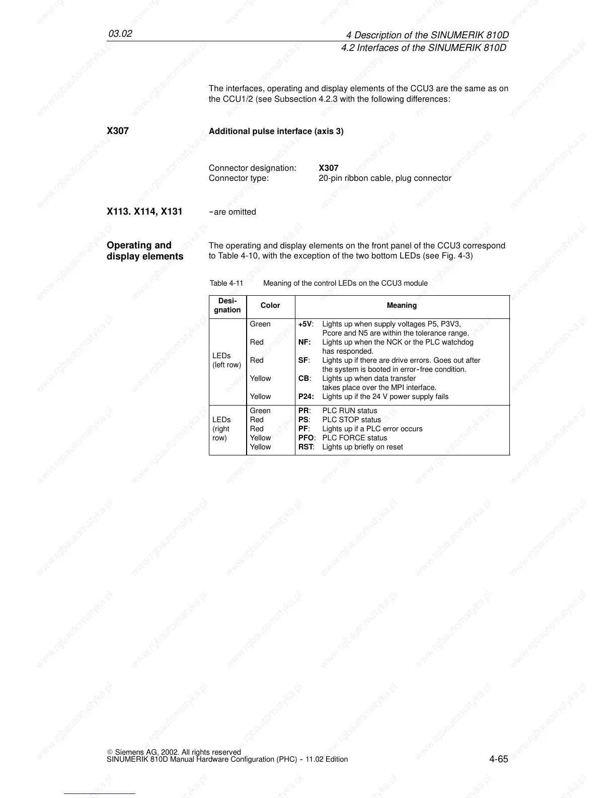
Table 4-11 Meaning of the control LEDs on the CCU3 module
Desi-
gnation
Color Meaning
LEDs
(left row)
Green
Red
Red
Yellow
Yellow
+5V: Lights up when supply voltages P5, P3V3,
Pcore and N5 are within the tolerance range.
NF: Lights up when the NCK or the PLC watchdog
has responded.
SF: Lights up if there are drive errors. Goes out after
the system is booted in error--free condition.
CB: Lights up when data transfer
takes place over the MPI interface.
P24: Lights up if the 24 V power supply fails
LEDs
(right
row)
Green
Red
Red
Yellow
Yellow
PR: PLC RUN status
PS: PLC STOP status
PF: Lights up if a PLC error occurs
PFO: PLC FORCE status
RST: Lights up briefly on reset
X307
X113. X114, X131
Operating and
display elements
4De
 Loading...


