)HHG
)HHG
)HHG
*
*
*
=
<
;
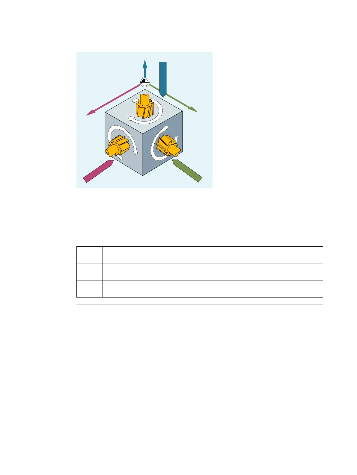
Syntax
G17/G18/G19, etc.
Meaning
G17: Working plane X/Y
Infeed direction Z, plane selection 1st - 2nd geometry axis
G18: Working plane Z/X
Infeed direction Y, plane selection 3rd - 1st geometry axis
G19: Working plane Y/Z
Infeed direction X, plane selection 2nd - 3rd geometry axis
Note
In the default setting, G17 (X/Y plane) is defined for milling and G18 (Z/X plane) is defined for
turning.
When calling the tool path correction G41/G42 (see Section "Tool radius compensation
(Page 251)"), the working plane must be defined so that the control can correct the tool length
and radius.
Example
The "conventional" approach for milling is:
1. Define working plane (G17 default setting for milling).
2. Select tool type (T) and tool offset values (D).
Fundamentals
2.8 Geometry settings
NC programming
146 Programming Manual, 12/2019, 6FC5398-2EP40-0BA0

 Loading...


