<n>: Number of the protection zone
Data type: INT
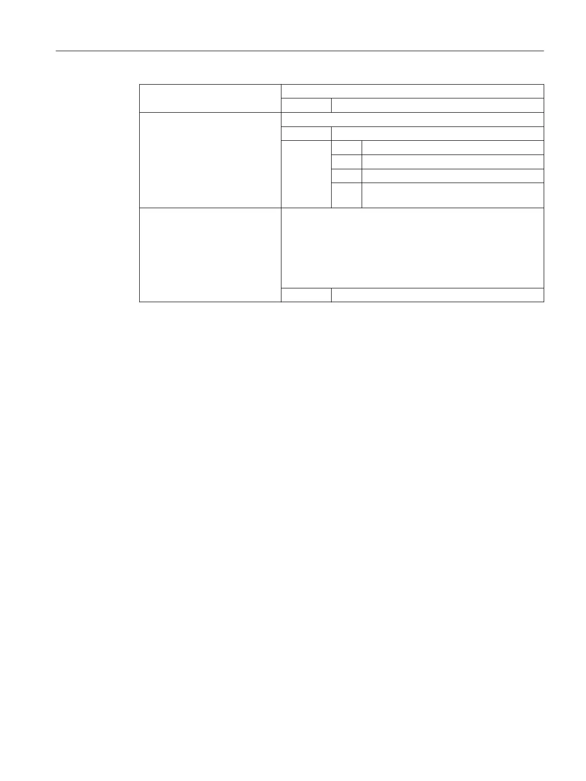
<Status>: The channel-specific activation status is set using this parameter
Data type: INT
Value: 0 Deactivate protection zone
1 Preactivate protection zone
2 Activate protection zone
3 Preactivate protection zone with conditional
stop
<XMov>,<YMov>,<ZMov>: Additive offset values in the X/Y/Z direction
The offset can take place in 1, 2, or 3 dimensions. The offset values
refer to:
● The machine zero for a workpiece-related protection zone
● The tool carrier reference point F for a tool-specific protection
zone
Data type: REAL
Example
Possible collision of a milling cutter with the measuring probe is to be monitored on a milling
machine. The position of the measuring probe is to be defined by an offset when the function
is activated.
The following protection zones are defined for this:
● A machine-specific and a workpiece-related protection zone for both the measuring probe
holder (n-PZ1) and the measuring probe itself (n-PZ2).
● A channel-specific and a tool-related protection zone for the milling cutter holder (c-PZ1),
the cutter shank (c-PZ2) and the milling cutter itself (c-PZ3).
The orientation of all protection zones is in the Z direction.
The position of the reference point of the measuring probe on activation of the function must be
X = -120, Y = 60 and Z = 80.
Work preparation
3.6 Protection zones
NC programming
Programming Manual, 12/2019, 6FC5398-2EP40-0BA0 579

 Loading...


