The following elements are defined for the example of the 3-axis milling machine:
Element Color Direction of movement
Table Green X, Y
Z axis Gray Z
Column Gray None
Tool holder Blue Z
Tool (when used) red Z
Machine zero None None
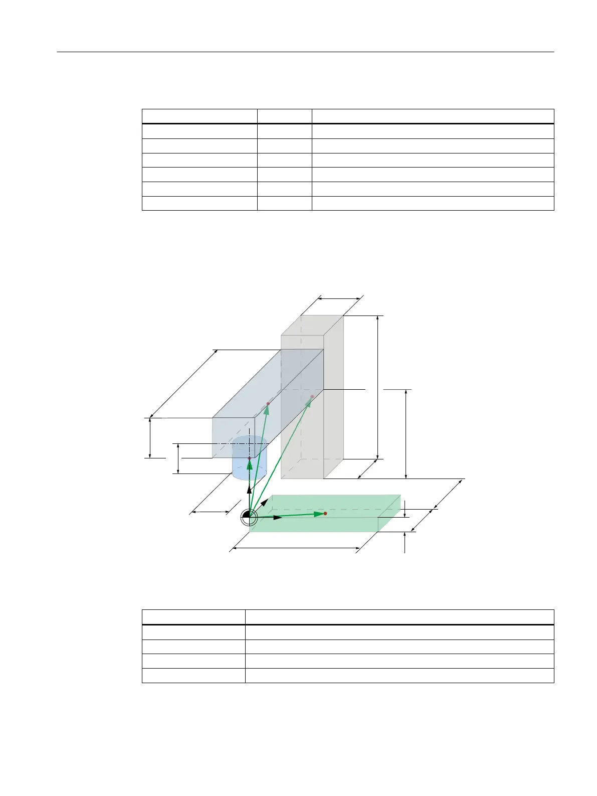
Geometry
Each machine-model element has a defined geometry and an offset vector to the element
center starting with the machine zero:
;
<
=
9
7
9
=$
9
6
9
7
ෘ
The following offset vectors are defined for the example of the 3-axis milling machine:
Element Offset vector
Tool holder V
tool
= (0; 0; 25)
Z axis V
ZA
= (0; 200; 130)
Column V
S
= (0; 570; 350)
Table V
T
= (100; 50; -25)
Collision avoidance
14.8 Collision avoidance example
SINUMERIK Operate (IM9)
Commissioning Manual, 12/2017, 6FC5397-1DP40-6BA1 321

 Loading...


