4.4.3 Connection box advanced
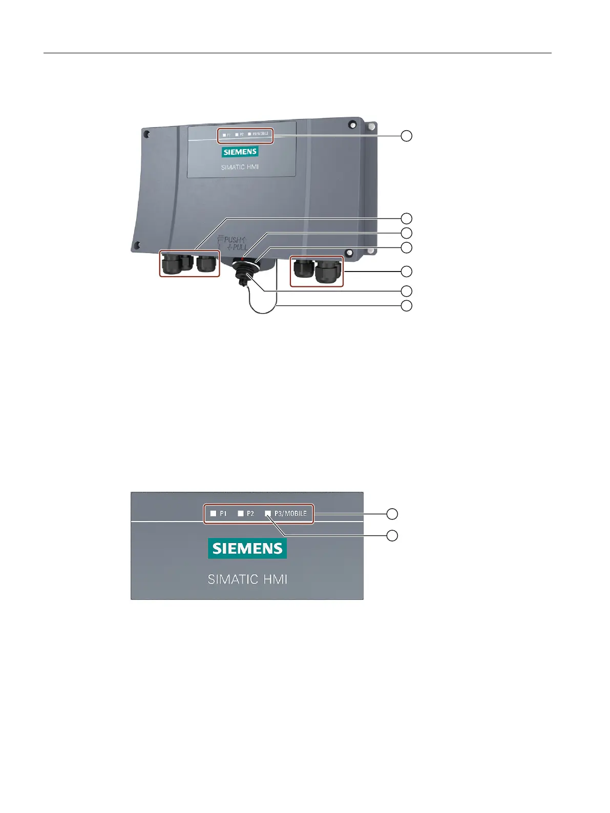
① LED display
② Screw glands for the data cables
③ Position mark
There is also a red position mark on the connecting cable. Align this with the position mark on the
connection box when connecting.
④ Connection socket for the connecting cable
⑤ Screw glands for the power supply cables and F signal cables
⑥ Sealing cap of the connection socket
⑦ Safety strap
Figure 4-3 Connection box advanced
On the front of the connection box, there are 3 LEDs which indicate the state of communication.
① LED display of the three Ethernet ports:
• P1: Fast Connector X1
• P2: Fast Connector X2
• P3: Connection socket for the HT 10
② LED
Basic functions of the LEDs:
• LED lights up green: Link present, no data transmission
• LED ashes yellow green or lights up yellow: Link present, transmitting data
Connecting
4.4 SIMATIC connection box
Handheld Terminal HT 10
34 Equipment Manual, 09/2020, A5E47430965B AA

 Loading...


