3. Insert the wire ends into the associated spring-loaded terminal as shown in the gures below.
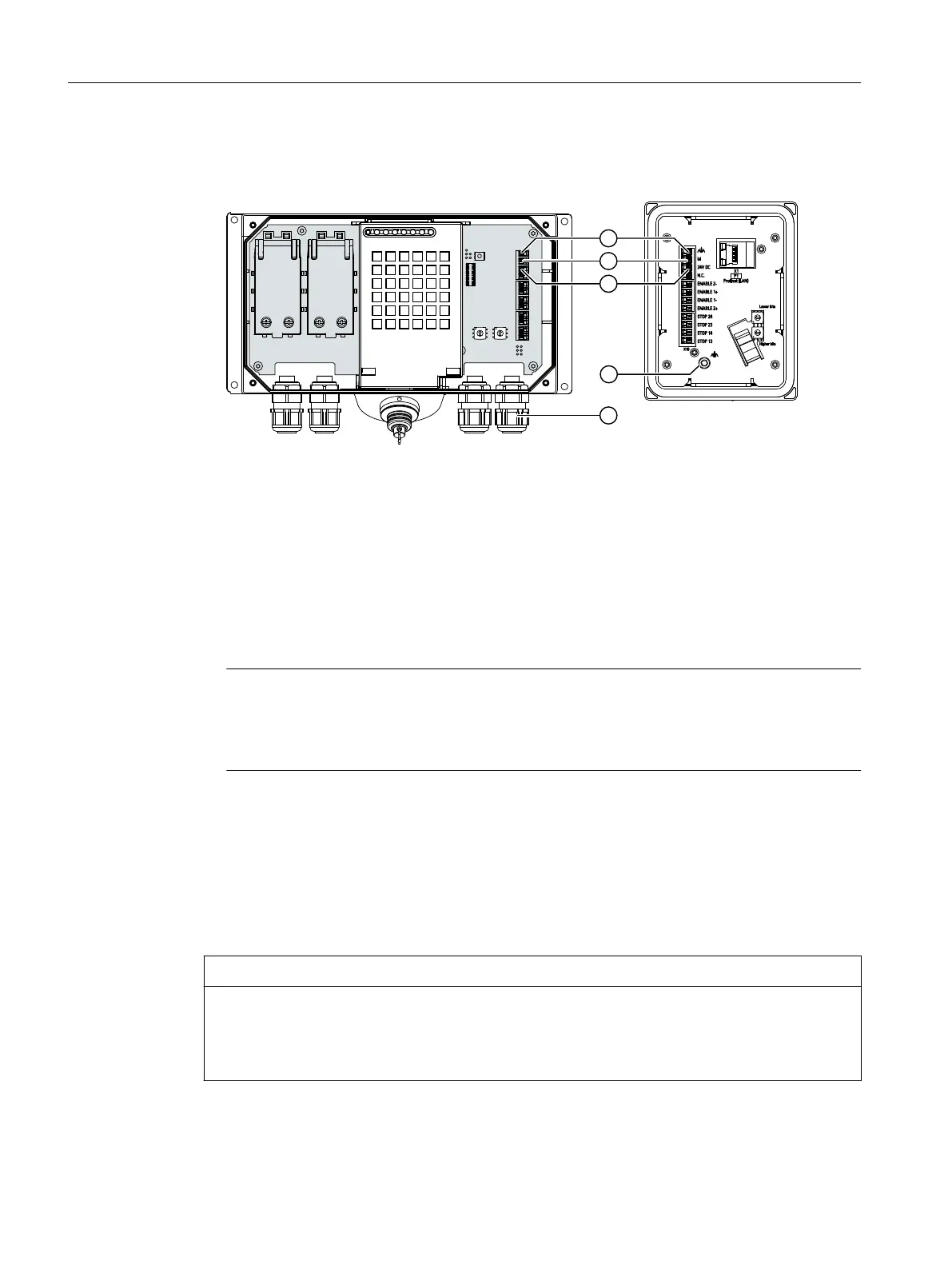
The gure below shows the contacts to be connected to the X10 terminal of the connection
box and the cable glands for cable entry.
① Connection for functional ground
② M24
③ P24
④ Screw gland
4. Connect the equipotential bonding conductor to the equipotential busbar.
5. Connect the equipotential bonding conductor to the terminal for the functional ground of
the connection box.
Connect the equipotential bonding conductor of the connection box as described in the
section "Equipotential bonding of connection boxes (Page 45)".
Note
Applies to oating system design:
Connect the terminal for GND 24 V from the 24 V power supply output to equipotential
bonding for uniform reference potential.
6. For connection box standard and connection box advanced:
When all the required work has been completed in the connection box, close it.
4.4.5.5 Connecting cables for a hardwired F-system
The signals for the emergency stop / stop button and the enabling button must be wired for a
hardwired F-system.
NOTICE
Length of the data cables to the connection box
If the permissible length of the data cables and signal cables between a connection box and the
plant is exceeded, malfunctions may occur. Keep the permissible length of ≤ 30 m for cables
between the connection box and the evaluation unit.
Connecting
4.4 SIMATIC connection box
Handheld Terminal HT 10
48 Equipment Manual, 09/2020, A5E47430965B AA

 Loading...


