Procedure
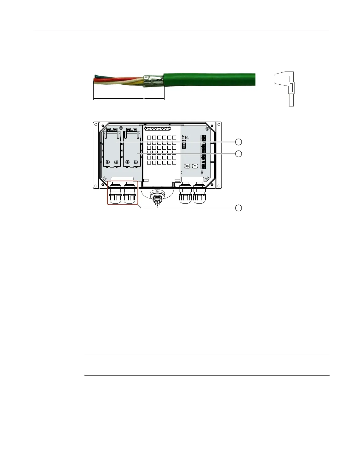
1. Strip the insulation on the Ethernet cable as shown in the gure below.
2. Open fast connector 1.
① Fast connector 1
② Fast connector 2
③ Screw gland
3. Push the Ethernet cable through the screw gland and connect the wires.
4. Close the fast connector.
Closing the fast connector establishes the contact to the wires in the Ethernet cable.
5. Tighten the screw cap on the screw gland.
The specied degrees of protection are only met when the screw cap has been tightened.
6. Once all the required work in the connection box has been completed, close it.
4.4.5.7 Setting the box ID of the connection box
You need to set a box ID for each connection box. If congured, the box ID can be read by the HMI
device and transmitted to the PLC.
The box ID allows connection point detection.
Note
You need to set a box ID for each connection box. Do not assign the same box ID twice.
Connecting
4.4 SIMATIC connection box
Handheld Terminal HT 10
Equipment Manual, 09/2020, A5E47430965B AA 51
 Loading...


