Procedure
1. Rotate the arrows of the rotary coding switch to the required hexadecimal value using a
suitable tool.
Values from "00" to "FF" (0 to 255 in decimal form) can be set with the rotary coding switches.
When setting the box ID:
– Use the value "00" only for the "Stop button evaluated by safety relay" operating mode.
– The value "FF" (255) is reserved and may not be used.
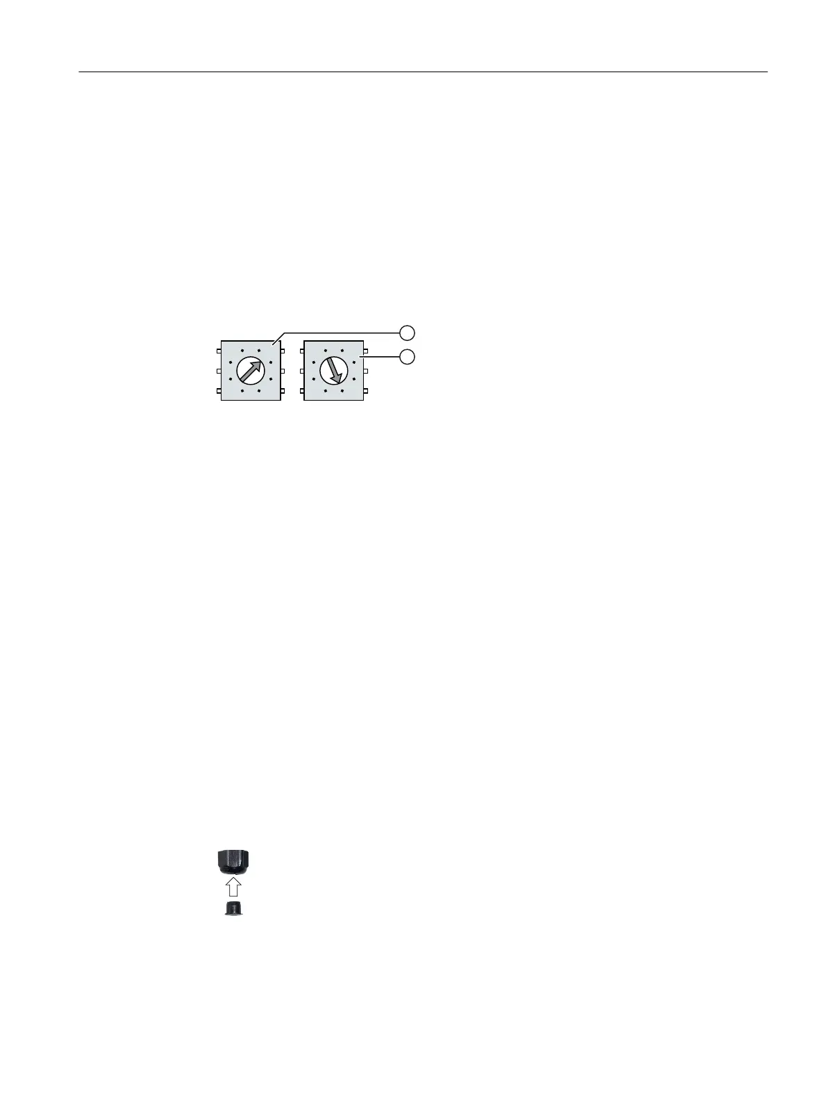
Example:
The gure below shows an example of the rotary coding switch for a connection box
standard. "27H" (39 in decimal form) is set for the box ID as an example.
① Rotary encoding switch for more signicant bits
In the connection boxes standard and advanced, it is the left rotary coding switch.
② Rotary encoding switch for less signicant bits
2. Once all the required work in the connection box has been completed, close it.
4.4.5.8 Secure cables and seal screw glands
After you have connected all cables to the connection box, close and secure the screw glands.
Requirement
For the connection box compact:
• 1 cable tie
• 1 diagonal cutter
• The connection box is closed.
Procedure
1. Check whether the cover is located in the cable glands that are not in use.
2. If a cover is missing, replace it.
3. Tighten the screw cap.
This will ensure IP65 degree of protection for the connection box standard or the connection box
advanced.
Connecting
4.4 SIMATIC connection box
Handheld Terminal HT 10
Equipment Manual, 09/2020, A5E47430965B AA 53

 Loading...


