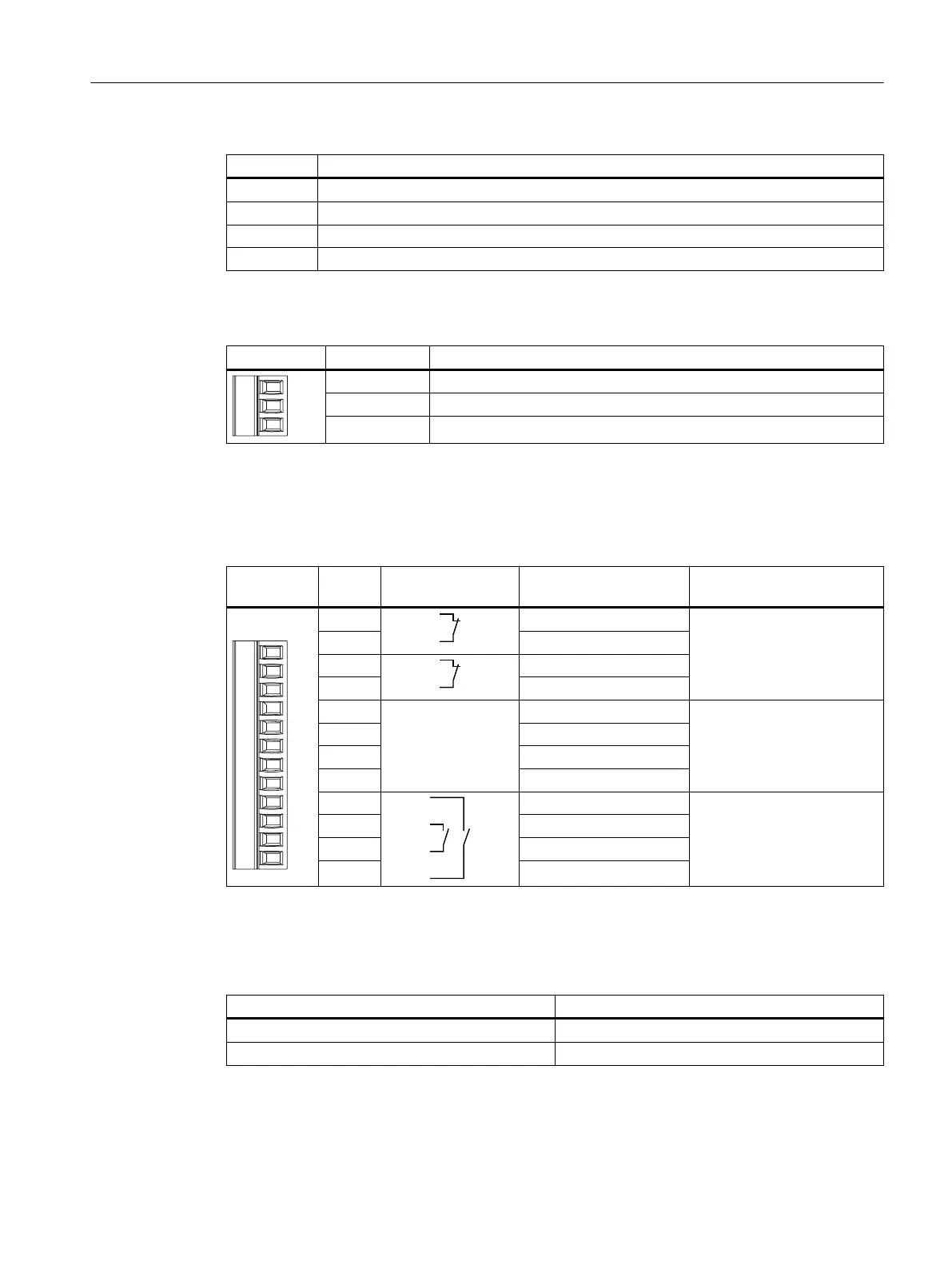
Pin Signal name
1 RD+
2 TD+
3 RD–
4 TD–
Terminal strip 1, for power supply, 3-pin
Pin Signal name
1 PE
2 M24
3 P24
Terminal strip 2, 12-pin
The safety and additional functions are connected to this terminal strip. The terminal strip is
mechanically coded to prevent it from being confused with terminal strip 1.
Pin Internal intercon‐
nection
Signal name Circuit
1 STOP13 Emergency Stop button
2 STOP14
3 STOP23
4 STOP24
5 +24 V
1)
Accompanying control sig‐
nals
6 CTRL32
1) 2)
7 PRESENT31
3)
8 +24 V
1)
9 ENABLE2+ Enabling button
10 ENABLE1–
11 ENABLE1+
12 ENABLE2–
1)
Applies only to the connection box advanced
2)
Active, if the Emergency Stop pushbutton is pressed
3)
Active if HT 10 is inserted
HT 10 on the connection box Signal at digital input of the control
Not connected "0"
Connected "1"
Connecting
4.4 SIMATIC connection box
Handheld Terminal HT 10
Equipment Manual, 09/2020, A5E47430965B AA 37

 Loading...


