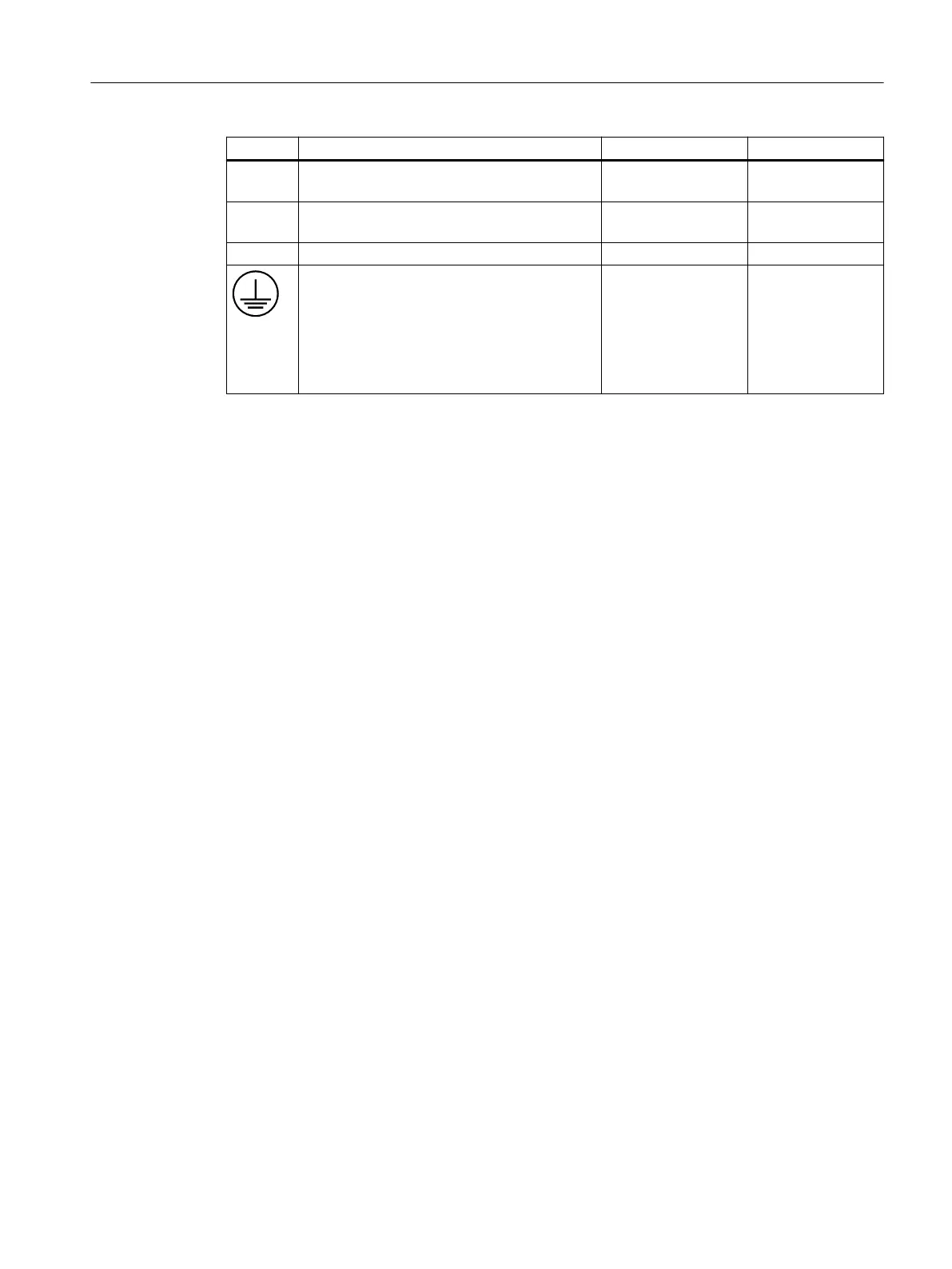
Interface Designation Max. cable length Type
X60 /
X61
Connections for 2 handwheels 10 m ix connector
X515
X516
Interfaces for custom made inputs and outputs 2 m 20-pin plug connec‐
tor
S2 DIP switch
Protective conductor connection As specied in the na‐
tional specications,
the necessary cross-
section must at least
be the same as the
cross-section of the
power supply cord
M5 screw
The following special requirements apply for the connection cables:
• The 24 V DC cable must be approved for temperatures up to 70 °C.
• Select the permitted conductor cross-section in accordance with the national regulations
(NEC, VDE, etc.) and the "Power supply connectors" table below. The basis for this can be the
output current of the 24 V DC power supply or the overcurrent protection device used in the
24 V circuit. If the 24 V power supply unit that is used has a short-circuit current greater than
50 A, a corresponding overcurrent protection device, which limits to this value, must be used
upstream of the product.
• Strip the cables (7 mm) for connection to the 24 V DC connector.
• Flame resistance of the 24 V DC cable in accordance with UL 2556 VW-1 / or tested in
accordance with IEC 60332-1-2.
• Observe the permissible bending radius of the cables.
• Route all the cables so that they cannot be crushed or pinched.
• Route all of the cables in such a way that they do not come into contact with chang edges.
Les câbles de raccordement doivent répondre aux conditions suivantes :
• Le câble 24 V CC doit être autorisé pour des températures jusqu'à 70 °C.
• Choisir la section de conducteur conformément aux prescriptions nationales (NEC, VDE,...)
dans le tableau ci-dessous "Power plug". Le courant de sortie de l'alimentation 24 V CC ou le
dispositif de protection contre les surintensités du circuit de commande 24 V peuvent servir
de base. Si le courant de court-circuit de l'alimentation 24 V CC utilisée est supérieur à 50 A,
placer un dispositif de protection contre les surintensité en amont du produit qui limite le
courant à cette valeur.
• Dénuder les conducteurs de raccordement au connecteur 24 V CC sur 7 mm.
• Tenir compte de la résistance au feu du câble 24 V CC selon UL 2556 VW-1/ ou satisfaisant aux
essais selon CEI 60332-1-2.
• Tenir compte du rayon de courbure admissible des câbles.
• Pose les câbles de manière à ce qu’ils ne pincent pas les câbles.
• Pose les câbles en évitant tout contact avec des arrêtes abrasives.
Operator control and display elements
3.3 Interfaces
ONE MCP Part 1: MCP xxxx
Equipment Manual, 07/2020, A5E50324729B AA 19
 Loading...