8.1.3 RI suppression measures
In addition to the protective grounding of system components, special precautions must be
taken to ensure safe, fault-free operation of the system. These measures include shielded signal
lines, special equipotential bonding connections, and isolation and shielding measures.
Shielded signal cables
• Use the specied cables for safe and fault-free operation of the system.
• Connect the shield conductively at both ends to the housing for digital signal transmission.
Cable denition
Denition:
• Signal cables (example)
– Data cables (Ethernet, PROFIBUS, sensor cables, etc.)
– Digital I/Os
– Cables for safety functions (emergency stop, enabling)
• Power cables (example)
– Low-voltage supply lines (230 VAC, +24 VDC, etc.)
– Motor cables
Rules for routing cables
In order to achieve the greatest possible EMC compatibility for the complete system (control,
power unit, machine), the following EMC measures must be carefully observed:
• If necessary, signal and power cables may cross one another (if possible at an angle of 90°),
but must never be laid close or parallel to one another.
• Only use cables approved by SIEMENS for the signal lines from and to the Control Unit.
• Signal cables must not be routed close to strong external magnetic elds (e.g. motors and
transformers).
• If signal lines cannot be routed a sucient distance away from other cables, they must be
installed in grounded cable ducts (metal).
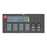
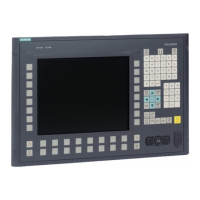
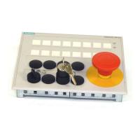
• The operator panel fronts, MCPs, MPPs, and full keyboards must be installed in metallically
enclosed EMC-compatible housings.
Further information on RFI suppression measures and the connection of shielded cables can be
found in the EMC Installation Guidelines.
Technical data
8.1 Supplementary electrical conditions
ONE MCP Part 1: MCP xxxx
Equipment Manual, 07/2020, A5E50324729B AA 57
 Loading...
