Connecting
5
5.1 interfaces
Overview
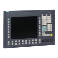
The relevant interfaces for cabling the control desk are located on the rear side of the machine
control panel.
Pin assignment of the interfaces
The pins of the component interfaces are assigned as specied in the tables below. Any
deviations are indicated at the relevant point.
Signal type
I Input
O Output
B Bidirectional (inputs/outputs)
V Power supply
- Ground (reference potential) or N.C. (not connected)
5.1.1 General requirements for the equipotential bonding
Potential dierences must be reduced through the use of equipotential-bonding cables to the
extent that the aected electronic components function awlessly. You must therefore observe
the following information when setting up the equipotential bonding:
• The lower the impedance of the equipotential-bonding cable or the bigger the cross-section
of the equipotential-bonding cable, the greater the equipotential bonding eect.
• If two parts of the system are connected to each other via shielded data cables, with shielding
that is connected at both ends to the grounding/protective cable, the impedance of the
additionally installed equipotential-bonding cable must not exceed 10% of the shield
impedance.
• The cross-section of an equipotential-bonding cable must be dimensioned for the maximum
owing compensating current.
Equipotential-bonding cables with a minimum cross-section of 16 mm
2
are required
between control cabinets.
• Use equipotential-bonding cables made of copper or galvanized steel. Connect the
equipotential-bonding cables via a broad surface area to the grounding/protective
conductor. Protect the equipotential-bonding cables against corrosion.
ONE MCP Part 1: MCP xxxx
Equipment Manual, 07/2020, A5E50324729B AA 33
 Loading...