Note
Warning for areas subject to NEC or CEC:
Safety notice for connectors with Ethernet marking:
A Ethernet or Ethernet segment, with all its associated interconnected equipment, shall be
entirely contained within a single low-voltage power distribution and within a single building.
The Ethernet is considered to be in an "environment A" according IEEE802.3 or "environment 0"
according IEC TR 62102, respectively.
Never make direct electrical connection to TNV-circuits (Telephone Network) or WAN (Wide Area
Network).
Pin assignment
The pin assignments of the interfaces can be found in Chapter "Connecting" > "Interfaces"
(Page 33).
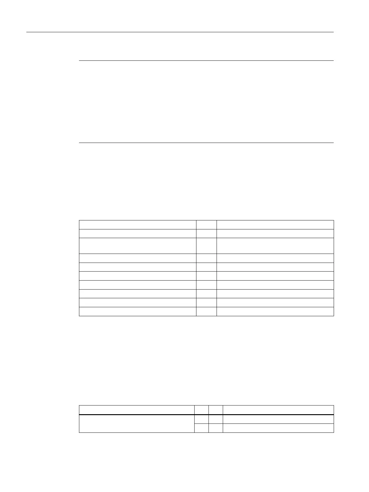
Power supply connectors
Connection type Strain-relief clamp connection
Connection screw M2.5 screw with cross-slot
Operating tool Screwdriver blade 0.6x3.5, PH0, PZ0 (DIN
5264, ISO 8764/2-PH, ISO 8764/2-PZ)
Specied tightening torque Nm 0.4 ... 0.5
Conductor cross-section min./max.
Solid mm² 1.3 … 3.3
Finely stranded mm² 1.3 … 3.3
With ferrule with collar DIN46228/4 mm² 1.3 … 2.5
With ferrule DIN46228/1 mm² 1.3 … 3.3
AWG cables, solid or stranded AWG 12 … 16
3.3.2 Description
Switch S1
MCP set up as PN
Table 3-1 General switch S1 setting
1-8 9 10 Meaning
See Table "Settings of switch S1" on on PN
o o IE (default)
The two switches S1-9 and S1-10 must be set to "on" for the PN functionality.
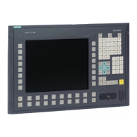
Operator control and display elements
3.3 Interfaces
ONE MCP Part 1: MCP xxxx
20 Equipment Manual, 07/2020, A5E50324729B AA
 Loading...