Functions
2.9 Jump of Voltage Vector
SIPROTEC, 7RW80, Manual
C53000-G1140-C233-1, Release date 10.2010
108
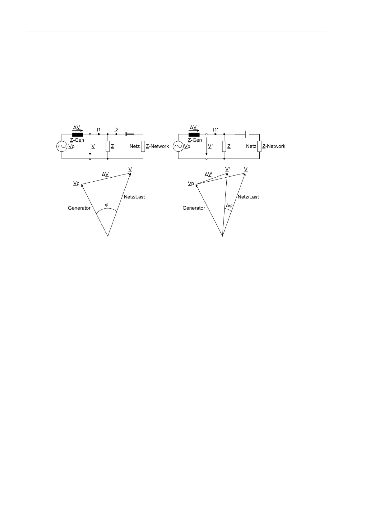
Measuring principle
For a three phase voltage connection, the vector of the positive sequence system voltage is calculated . For a
single-phase connection, the connected single-phase voltage is evaluated. The phase angle change of the
voltage vector is determined over a delta interval of 2 cycles. The presence of a phase angle jump indicates an
abrupt change of current flow. The basic principle is shown in Figure 2-32. The diagram on the left shows the
steady state, and the diagram on the right the vector change following a load shedding. The vector jump is
clearly visible.
Figure 2-32 Voltage Vector Following Load Shedding
The function features a number of additional measures to avoid spurious tripping, such as:
• Correction of steady-state deviations from rated frequency
• Frequency operating range limited to f
N
± 3 Hz
• Detection of internal scanning frequency changeover (Scanning frequency adjustment)
• Minimum voltage for enabling
• Blocking on voltage connection or disconnection
Logic
The logic is shown in Figure 2-33. The phase angle comparison determines the angle difference, and compares
it with the set value. If this value is exceeded, the vector jump is stored in a RS flip-flop. Trippings can be
delayed by the associated time delay.
The stored pickup can be reset via a binary input, or automatically by a timer (address 4604 T RESET).
The vector jump function becomes ineffective on exiting the admissible frequency band. The same applies for
the voltage. In such a case the limiting parameters are V MIN and V MAX.
If the frequency or voltage range is not maintained, the logic generates a logical 1, and the reset input is con-
tinuously active. The result of the vector jump measurement is suppressed. If, for instance, the voltage is con-
nected, and the frequency range is correct, the logical 1 changes to 0. The timer T BLOCK with reset delay
keeps the reset input active for a certain time, thus preventing a pickup caused by the vector jump function.
If a short-circuit causes the voltage to drop abruptly to a low value, the reset input is immediately activated to
block the function. The vector jump function is thus prevented from causing a trip.

 Loading...


