Functions
2.11 Monitoring Functions
SIPROTEC, 7SJ62/64, Manual
C53000-G1140-C207-2, Release date 01.2008
210
Note
The setting under address 5310 BLOCK PROT. has no effect on the flexible protection functions. A separate
blocking can be selected for that purpose.
The function may be disabled in address 5301 FUSE FAIL MON., e.g. when performing asymmetrical tests.
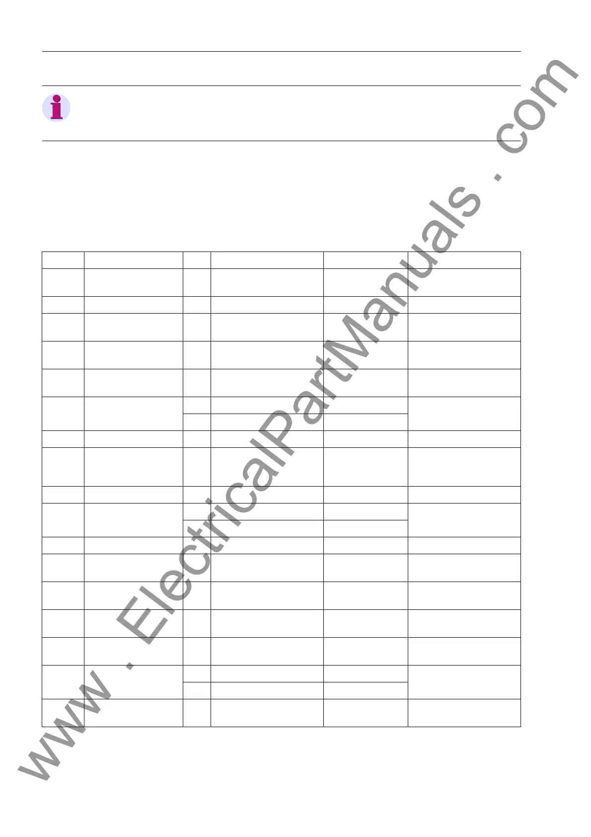
2.11.1.9 Settings
The table indicates region-specific default settings. Column C (configuration) indicates the corresponding sec-
ondary nominal current of the current transformer.
Addr. Parameter C Setting Options Default Setting Comments
5201 VT BROKEN WIRE ON
OFF
OFF VT broken wire supervi-
sion
5202 Σ V> 1.0 .. 100.0 V 8.0 V Threshold voltage sum
5203 Vph-ph max< 1.0 .. 100.0 V 16.0 V Maximum phase to phase
voltage
5204 Vph-ph min< 1.0 .. 100.0 V 16.0 V Minimum phase to phase
voltage
5205 Vph-ph max-min> 10.0 .. 200.0 V 16.0 V Symmetry phase to phase
voltages
5206 I min> 1A 0.04 .. 1.00 A 0.04 A Minimum line current
5A 0.20 .. 5.00 A 0.20 A
5208 T DELAY ALARM 0.00 .. 32.00 sec 1.25 sec Alarm delay time
5301 FUSE FAIL MON. OFF
Solid grounded
Coil.gnd./isol.
OFF Fuse Fail Monitor
5302 FUSE FAIL 3Vo 10 .. 100 V 30 V Zero Sequence Voltage
5303 FUSE FAIL RESID 1A 0.10 .. 1.00 A 0.10 A Residual Current
5A 0.50 .. 5.00 A 0.50 A
5307 I> BLOCK 0.10 .. 35.00 A; ∞ 1.00 A I> Pickup for block FFM
5310 BLOCK PROT. NO
YES
YES Block protection by FFM
8101 MEASURE. SUPERV OFF
ON
ON Measurement Supervision
8102 BALANCE V-LIMIT 10 .. 100 V 50 V Voltage Threshold for
Balance Monitoring
8103 BAL. FACTOR V 0.58 .. 0.90 0.75 Balance Factor for Voltage
Monitor
8104 BALANCE I LIMIT 1A 0.10 .. 1.00 A 0.50 A Current Threshold for
Balance Monitoring
5A 0.50 .. 5.00 A 2.50 A
8105 BAL. FACTOR I 0.10 .. 0.90 0.50 Balance Factor for Current
Monitor
www . ElectricalPartManuals . com

 Loading...


